
LED Strip Light Channel Types and Fit
A strip advertised as 10 mm wide does not automatically fit every channel promoted for 10 mm tape. Measure the components you will actually install.
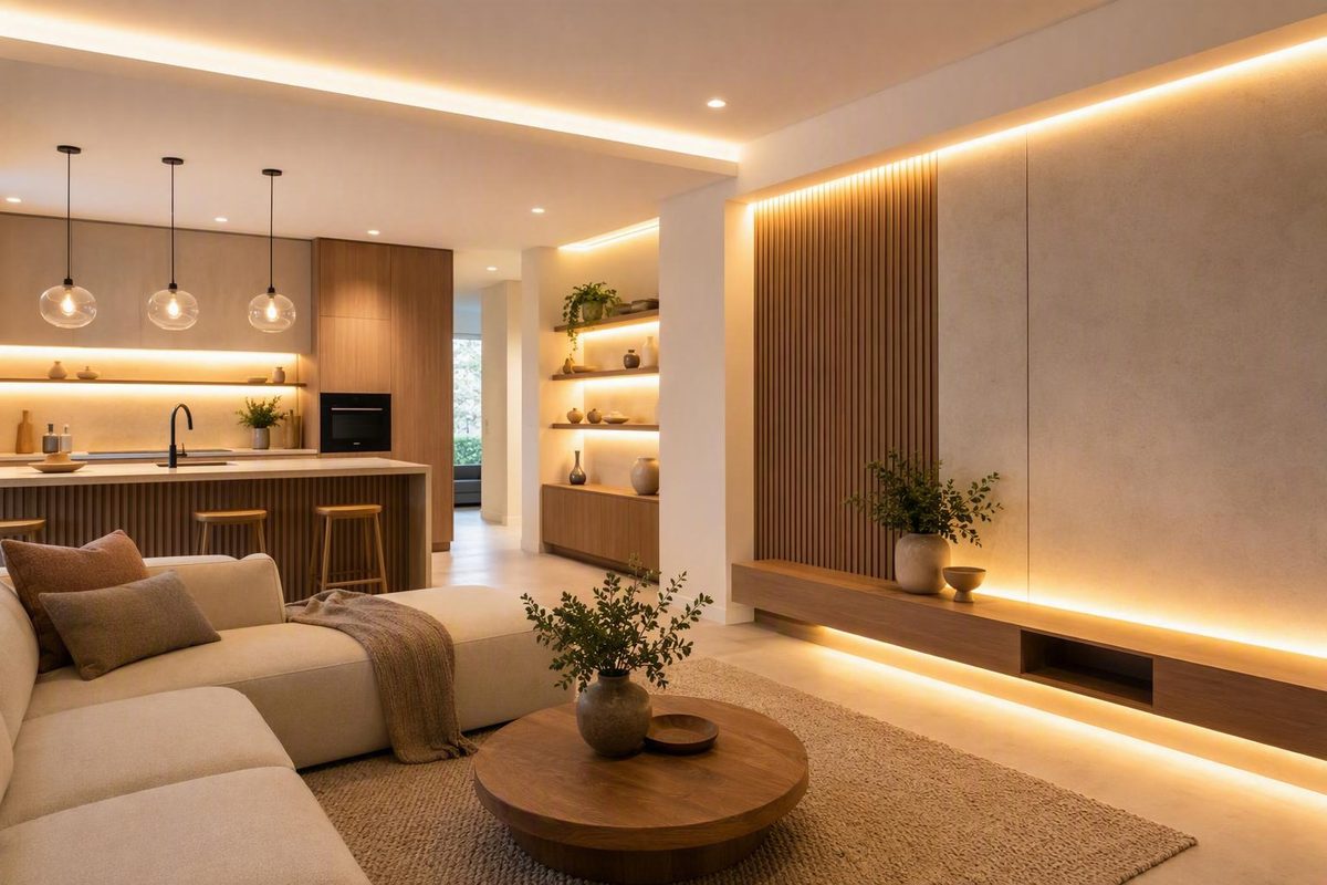
An LED strip light channel can turn exposed tape into a straight, finished line of light, but appearance is only one part of the choice. The profile must also fit the tape, connections, wiring, diffuser, end caps, mounting surface, and surrounding construction.
Start with the physical constraint: Can the surface be routed or opened? May the aluminum remain visible? Where should the light point? Then verify the actual component dimensions, evaluate diffusion with a lit sample, and confirm that the complete assembly is documented for its intended environment.
What an LED Strip Light Channel Is—and What It Can Actually Do
An LED strip light channel is a housing that holds flexible LED tape and usually accepts a removable lens or diffuser. Sellers and installers also use the terms LED profile, aluminum extrusion, track, and housing. These terms overlap, although individual vendors may use them differently.
The channel is only one part of the installation:
- Profile or base: The aluminum or plastic body that supports the tape.
- Diffuser or lens: The clear, frosted, milky, or opal cover over the LEDs.
- End caps: Pieces that close or finish the ends, sometimes with wire-entry openings.
- Clips, brackets, and fasteners: Hardware used to secure the profile.
- LED tape: The light source.
- Wire and connections: Soldered leads, connectors, extensions, and cable entries.
- Driver: The power supply selected for the strip voltage and load.
- Dimmer or controller: Optional control equipment compatible with the strip and driver.
Do not assume that “channel” means a complete assembly. Some products include the profile, diffuser, end caps, and mounting parts; others sell nearly every component separately. Diode LED, for example, distinguishes complete bundles from individual channels, lenses, accessory kits, and mounting accessories in its channel-profile catalog.
What a channel can reasonably do
A suitable channel can:
- Keep the tape straight. A rigid profile provides a consistent mounting line along shelves, cabinets, ceilings, and architectural details.
- Reduce direct contact. The profile and cover can provide limited separation from fingers, stored objects, dust, and routine handling.
- Conceal components. The body can hide the tape edge and some wiring, while end caps finish the termination.
- Create a finished edge. A properly aligned profile looks more deliberate than tape adhered directly to a visible surface.
- Help blend individual LEDs. The diffuser and the distance between the emitters and cover can make separate diodes appear more like a continuous line.
Evaluate these functions separately. A profile that shields the tape may still show bright dots. A deep profile that blends light effectively may be too large for a shelf. A trimless profile may look integrated but complicate later access.
Aluminum can spread heat away from the tape, but this does not establish adequate thermal performance for every strip. The result depends on the tape, profile, mounting conditions, airflow, and ambient temperature. Without product-specific thermal data, do not assume that a profile will extend LED life by a stated amount or safely accommodate a particular load.
When a channel is optional
A channel is not essential in every project. Tape hidden inside a cove, behind a valance, or above a cabinet may already be out of sight and may illuminate a reflecting surface instead of facing the viewer. In those situations, a diffuser may offer less visual benefit.
A channel also cannot correct:
- An incompatible or undersized driver
- Excessive voltage drop
- Incorrect conductor sizing
- Reversed polarity
- An unsuitable dimmer or controller
- Inaccessible connections
- Tape used outside its documented environment
- A mounting arrangement that conflicts with the strip manufacturer’s instructions
Treat the channel as one component of the lighting system, not as a universal remedy.
Choose the Profile Type by Mounting Constraint
Choose the mounting style before comparing finishes or diffuser shapes. Use this decision path:
- Can the surface be cut, routed, or opened?
- Can the cavity accommodate the complete profile, wiring, and end treatment?
- May the aluminum body remain visible?
- Which direction should the light face?
- Can the diffuser and tape remain accessible after installation?
- Does the location require documented environmental or mechanical performance?
Catalogs commonly group channels as surface, recessed, corner, drywall or mud-in, millwork, stair, suspended, flexible, wall-wash, floor, and in-ground forms. These categories are useful starting points, but family names are not standardized. Compare drawings, mounting instructions, and documented ratings rather than relying on labels such as “T12,” “DiffuseMax,” “neon effect,” or “professional.”
Main profile types compared
| Profile type | Required substrate work | Visible finish | Typical beam direction | Relative installation difficulty | Maintenance access | Representative applications |
|---|---|---|---|---|---|---|
| Surface-mounted | No routed recess; attaches to the finished face | Aluminum body generally remains visible | Usually outward or downward | Low to moderate | Usually good if the diffuser remains removable | Finished cabinets, shelves, rentals, concrete surfaces, retrofits |
| Recessed | Precise slot, groove, or cavity | Usually diffuser plus narrow flanges | Out from the recess | Moderate to high | Product- and finish-dependent | Millwork, shelves, ceilings, cabinets |
| Mud-in or trimless | Drywall opening plus joint-compound and finish work | Diffuser or light opening remains visible; flange is concealed | Usually outward from a wall or ceiling | High | Must be planned before finishing | Drywall ceilings, walls, reveals, curves |
| Corner or angled | Mounting surface in or near a corner | Usually visible unless concealed by trim | Redirected away from the corner | Low to moderate | Usually good | Under-cabinet work lighting, displays, wardrobes |
| Millwork | Routed slot or purpose-built cavity | Flush or nearly flush | Depends on profile geometry | Moderate to high | Depends on diffuser removal | Cabinetry, shelves, furniture |
| Flexible or bendable | Repeated support along a documented curve | Varies | Follows the permitted bending plane | Moderate to high | Product-dependent | Arches, curved millwork, curved drywall details |
| Suspended | Suspension hardware, feeds, and suitable attachment | Fully visible architectural fixture | Downward, upward, or both | High | Product-dependent | Islands, desks, commercial interiors |
| Cove or indirect | Ledge, pocket, or setback | Usually concealed | Toward a reflecting wall or ceiling | Moderate | Depends on cove access | Perimeter ceilings, indirect wall lighting |
| Wall-wash or wall-graze | Controlled setback and aiming | Visible or recessed | Across or down a wall | Moderate to high | Product-dependent | Textured walls, displays, architectural accents |
| Stair | Profile-specific preparation | Varies | Toward a tread, riser, or adjacent surface | High | Must be established from product documentation | Stairs and step details |
| Floor, walk-over, or in-ground | Purpose-built recess and complete installation detail | Diffuser or top face exposed | Upward or lateral | Very high | Often difficult | Floors, paths, landscape, paving |
Surface profiles attach to a finished face without a routed recess. They are useful where cutting is impractical, but their height and finish remain part of the view. Recessed profiles require a slot and enough cavity depth for the body, connections, and wire entry. Their flanges may cover the cut edge, but “recessed” does not necessarily mean that only the diffuser will be visible.
Mud-in profiles differ from ordinary recessed profiles. Their flanges or beads are covered by the surrounding drywall finish to create a trimless result. This commits the profile to the finished surface, so alignment, finish buildup, lens removal, and future access must be resolved from the selected system’s drawing and installation instructions before finishing begins.
Corner and angled profiles redirect light away from an inside corner. They can aim under-cabinet light toward a work surface or direct display lighting toward merchandise. The category name alone does not predict coverage; diffuser shape, placement, cabinet geometry, and viewer position also affect the result.
Specialty catalogs list suspended, millwork, cove, wall-wash, flexible, curved-drywall, stair, floor, walk-over, and in-ground forms. Category availability does not establish suitability. A flexible product still needs documentation for its permitted bending plane and radius. Likewise, a product described as “walk-over” or “in-ground” needs product-level mechanical and environmental specifications before it is selected for that use.
Measure the Strip, Connector, Channel, and Recess Before Buying
A strip advertised as 10 mm wide does not automatically fit every channel promoted for 10 mm tape. The bare circuit board may fit while a sleeve, solder joint, clip connector, wire bundle, or cable exit does not.
Measure the components you will actually install rather than relying on a nominal family size.
Measurement worksheet
Record the following dimensions in one unit system and compare them with the exact product drawing:
| Item to measure | Why it matters |
|---|---|
| Actual tape width | Determines the minimum clear width at the channel floor |
| Coating or sleeve width | Sealed tape may be wider than the circuit board |
| Coating or sleeve height | May reduce clearance below the diffuser |
| Width across solder joints | Solder may extend beyond the tape edge |
| Connector width | Clip connectors may be wider than bare tape |
| Connector height | A connector may interfere with a shallow diffuser |
| Wire and bundle size | Conductors need enough internal and exit clearance |
| Cable bend and exit clearance | The assembly needs space at the end or side entry |
| Usable internal channel width | This—not the external width—determines basic tape fit |
| Clear internal depth | Determines room for tape, connections, and light mixing |
| Diffuser-tab intrusion | Snap tabs may narrow the usable opening |
| External channel width and height | Determines whether the body fits the surface or cavity |
| Flange or plaster-bead width | Determines visible edge and finish area |
| Required recess width and depth | Determines the routed slot or opening |
| End-cap thickness | Changes the finished length and termination allowance |
| End-cap wire opening | Must suit the planned cable-entry arrangement |
| Clip or bracket envelope | Hardware may add space behind or beside the profile |
Use calipers where practical, especially for shallow channels and coated tape. Measure the widest and tallest point of the assembled connection rather than only the center of the strip.
Seller listings illustrate why nominal dimensions cannot be generalized. EnvironmentalLights lists strip-light bars for nominal 10 mm and 12 mm strips in its channel-system catalog. Separate Amazon listings state maximum strip widths of 12 mm and 15 mm for two different profiles; those figures apply only to the products shown and do not establish an industry sizing standard (Amazon listing results).
HitLights describes many of its surface-profile options as commonly fitting many 8–10 mm strips. The qualifiers matter: “many” and “commonly” do not establish universal compatibility, particularly once coatings, connectors, and tolerances are included (HitLights selection guide).
Read the drawing, not just the title
Product titles may emphasize external width, diffuser width, or nominal tape size. What you need is the usable internal width after diffuser tabs and other internal features are accounted for.
For recessed and mud-in profiles, identify whether each published dimension refers to:
- The aluminum body
- The required routed opening
- The visible diffuser
- The top flange
- The complete plaster bead
Listing summaries do not always describe these dimensions consistently. Use the drawing and instructions for the exact product revision rather than transferring dimensions from a similar-looking profile.
Verify that every accessory belongs to the same system. A diffuser of the same nominal length may use a different snap geometry. End caps may fit only one base or lens shape. Mounting clips may suit a surface profile but not a visually similar recessed version. An internal connector may be too tall even when the bare tape fits.
Dry-fit before routing
Obtain a short sample and assemble it with:
- The actual LED tape
- The actual connector or soldered lead
- The intended wire
- The diffuser
- Both end-cap styles, if one includes a wire opening
- A mounting clip or bracket, where applicable
Power the sample at the intended control levels. Confirm that the diffuser closes normally and that the complete connection fits without being forced. Complete this check before routing cabinetry, opening drywall, or ordering a large custom-cut batch.
Match the Diffuser and Channel Depth to the Desired Light
A diffuser cannot be selected independently of the tape and channel. The visible result comes from the relationship among:
- Diode pitch, or spacing between emitters
- LED package or COB construction
- Distance from the emitting surface to the lens
- Channel width and internal geometry
- Diffuser material, thickness, texture, and opacity
- Output level
- Viewer distance and angle
- Whether the diffuser is directly visible
Clear, frosted, milky, and opal covers
A clear lens generally leaves a more direct view into the channel. It can be useful when physical coverage matters more than concealment, but individual diodes, solder joints, and surface irregularities are more likely to remain visible.
A frosted diffuser scatters the image more than a clear cover and may provide a compromise between concealment and output.
A milky or opal diffuser generally prioritizes concealment. It may make the light line appear smoother, but increased opacity can also reduce usable output.
These descriptions are qualitative. There is no responsible universal transmission percentage for labels such as “clear,” “frosted,” “milky,” or “opal” because materials, thicknesses, textures, geometries, and test methods vary. Compare product-specific optical data where it is available.
Flat and curved or arc diffusers are also form choices. A curved cover can change the apparent shape of the light line and its side visibility, but shape alone does not establish beam angle, glare control, or transmission.
Why deeper channels can help—but cannot guarantee “dotless” light
Increasing the chip-to-lens distance gives light from adjacent emitters more room to overlap before reaching the diffuser. This may improve blending. It does not guarantee a continuous line because widely spaced LEDs, a relatively transparent diffuser, high output, or close viewing can still reveal bright points.
A retailer-authored guide presents a relationship between LED spacing and chip-to-lens depth as a rule of thumb. Treat it only as an initial screening idea, not a validated guarantee, because actual dot visibility depends on several variables at once (Bees Lighting channel guide).
COB and high-density SMD tape reduce the apparent spacing between emitting points. They may therefore blend more readily in a shallow profile than low-density tape. Neither technology guarantees a perfectly continuous line through every diffuser at every output level and viewing distance.
Likewise, a seller’s “dotless” description may apply only to a specified channel, tape, and lens combination. Do not transfer the claim to another strip or installation geometry.
Troubleshooting visible dots and glare
If a mock-up shows distinct points or uncomfortable brightness, compare these possible changes:
- Test denser tape or COB tape. Smaller apparent gaps give the diffuser less work to do.
- Test a deeper channel or greater setback. More mixing distance may soften the diode image.
- Try a more opaque compatible diffuser. Compare the improvement in concealment with the change in output.
- Reduce output if the application permits it. Check the result at realistic control levels.
- Move the channel out of direct sight. A placement change may reduce direct lens visibility.
- Change the aiming. A compatible angled or cut-off profile may redirect the brightest view.
- Test reflected light. A cove, valance, or rear-facing shelf detail can illuminate a surface rather than present the lens directly.
The most reliable comparison is a lit mock-up using the intended tape, channel, diffuser, control level, surrounding colors, and viewing position. Examine it from the places where people will normally stand or sit before cutting a prominent ceiling, wall, shelf, or cabinet.
Match the Channel to the Application and Substrate
There is no universally best LED strip light channel. Selection depends on where the profile is mounted, what it must illuminate, where the viewer stands, what substrate work is possible, and how the assembly will be serviced.
Under cabinets and counters
Surface and recessed profiles can both work. A surface profile avoids routing and is usually easier to add to finished cabinetry. A recessed profile can create a flush detail, but its required slot, flange, and depth must fit the available material according to the cabinet and profile documentation.
Placement is a design variable rather than a universal rule. Test front, center, and rear positions where practical. An angled or cut-off profile may help redirect the light or reduce direct visibility, but the result depends on the cabinet, work surface, profile, and viewer position.
Check connection clearance at transitions and plan how the tape will be replaced. Before fixing the profile, confirm whether the diffuser can be removed with the cabinet in place.
Shelves, displays, wardrobes, and millwork
Shallow recessed profiles are useful where the aluminum edge should be minimized, but available material thickness limits the possible recess. Confirm the body depth, flange width, required opening, and installation method before routing.
Consider whether the aluminum finish will be visible from the front or side. Black, white, and aluminum finishes may blend into the millwork or become a deliberate detail. Plan wire exits so they do not emerge into the visible shelf opening.
In wardrobes and furniture, include doors, hinges, drawer slides, clothing, and stored objects in the mock-up. A diffuser provides limited separation from the tape; it should not be treated as documented impact protection unless the product specifications say so.
Coves and indirect lighting
Cove lighting hides the strip from normal view and directs light toward a wall or ceiling. Setback affects the visible spread and brightness pattern. Because the viewer mainly sees reflected light rather than the diffuser, maximum diffuser opacity may not be necessary.
A channel can still keep the tape aligned and provide a removable base. However, a deep or highly opaque assembly may not be useful when the strip is already fully concealed. Test the complete cove geometry before finalizing the ledge.
Corners
A corner profile changes beam direction. Under a cabinet, it may direct light toward a countertop; inside a display, it may aim toward merchandise; near a wall, it may emphasize surface texture.
Do not assume that a category angle will provide the intended coverage. Mock up the selected profile and inspect:
- Where the brightest area lands
- Whether the diffuser is visible from normal eye level
- Whether the installation creates an unwanted shadow
- Whether glossy surfaces show distracting reflections
- Whether doors or shelves interrupt the beam
Drywall ceilings and walls
A conventional recessed profile sits in an opening and may retain visible flanges. A mud-in profile uses flanges or beads intended to be covered by the surrounding finish.
Before installation, use the selected system’s drawing and instructions to resolve:
- Body, flange, and bead dimensions
- Required cavity depth
- Intended finish treatment
- Alignment across the planned run
- Wire-entry locations
- Access to the tape, connections, and driver
- The specified method for removing the diffuser
Do not assume that two similar-looking mud-in profiles use the same finishing or lens-removal method.
Curves
Choose a flexible or bendable product only when its documentation supports the required geometry. Confirm:
- The documented bend radius
- The permitted bending plane
- Whether the diffuser follows the same curve
- The specified support or fastening method
- Whether the profile is shaped before or after lens installation
A “bendable” category label does not establish unlimited flexibility. For example, Home Depot lists an Armacost bendable surface-mount channel as a five-pack with a translucent polycarbonate diffuser, but the supplied listing summary does not provide a bend radius (Home Depot product page). That missing specification must be resolved before using the product on a particular curve.
Stairs, floors, and in-ground locations
These applications require more than a profile with the right shape. Before selection, obtain product-level documentation for the characteristics relevant to the project, which may include:
- Intended orientation and application
- Load conditions
- Impact resistance
- Lens retention
- Exposed-surface characteristics
- Environmental sealing
- Drainage requirements
- Installation and maintenance procedures
Catalog labels such as “stair,” “floor,” “walk-over,” and “in-ground” do not replace those specifications. Diode LED, for example, lists walk-over profiles for in-floor applications but does not provide load ratings in the supplied category-page information.
Substrate and mounting checks
| Substrate | Possible mounting approaches | Documentation and fit checks |
|---|---|---|
| Wood or cabinetry | Clips, screws, routed recess, brackets, or an approved adhesive method | Available material thickness, required opening, fastener method, finish compatibility, wire route, lens access |
| Drywall | System-specified supports, brackets, recessed framing, or mud-in construction | Profile instructions, support locations, flange dimensions, finish method, cavity conflicts, future access |
| Concrete or masonry | Surface brackets, specified anchors, or a documented adhesive method | Product mounting instructions, surface condition, cable route, and environmental exposure |
| Tile or glass | A product-approved mounting method | Compatibility with the finished surface, preparation requirements, cure instructions, and removal implications |
| Metal | Clips, brackets, screws, or another documented method | Profile instructions, edge and cable-entry treatment, material compatibility, and finish condition |
No adhesive should be assumed suitable merely because mechanical attachment is inconvenient. Use only a method documented for the selected profile, adhesive, substrate, and environment.
Check Every Part of the Channel System Before Ordering
A low profile price can be misleading if the diffuser, end caps, clips, and cutting services are separate. Build the bill of materials before comparing systems.
Bill-of-materials checklist
- [ ] Profile
- [ ] Compatible diffuser or lens
- [ ] Solid end caps
- [ ] End caps with the required wire-entry arrangement
- [ ] Mounting clips, brackets, or suspension hardware
- [ ] Product-specified fasteners or adhesive
- [ ] LED tape
- [ ] Feed and interconnecting wire
- [ ] Compatible connectors or soldered leads
- [ ] Driver selected for the strip voltage and load
- [ ] Compatible dimmer or controller
- [ ] Product-specified conductor protection or strain-relief parts
- [ ] Required seals, gaskets, end treatments, or cable-entry components
- [ ] Corner, joint, or transition parts
- [ ] Spare diffuser or end caps where future matching may be difficult
Complete kits versus separate components
A complete kit or bundle reduces selection work. The base and diffuser should already use the correct mating geometry, and end caps or clips may be included. The tradeoff is usually less choice in lens, finish, cap style, and mounting method. Always check the package list rather than relying on the word “complete.”
A component-based system provides more flexibility. You may be able to choose among lens types, finishes, specialized end caps, and mounting accessories. The main risk is ordering visually similar parts from incompatible profile families.
| Factor | Kit or bundle | Separate components |
|---|---|---|
| Convenience | Usually higher | Requires more specification work |
| Compatibility risk | Lower if the package is accurately described | Higher unless every component is verified |
| Finish and diffuser choice | Often limited | Usually broader |
| Customization | Moderate | High |
| Replacement access | Depends on continued kit support | Can be good if the component family remains available |
| Cost clarity | Easier initially | Requires a complete component total |
| Waste control | Pack quantities may create surplus | Individual ordering may reduce or increase waste |
Before ordering, confirm:
- Profile and diffuser length
- Number of pieces in each package
- Aluminum finish and lens color
- Exact included accessories
- Clip and end-cap quantities
- Replacement-lens availability
- Solid and wire-entry cap options
- Whether cutting includes both profile and diffuser
- Stated cut tolerances
- Whether custom cutting changes return eligibility
- Shipping limitations for long profiles
Compare total installed cost
Calculate cost per usable unit length only after adding:
- Profiles
- Diffusers
- End caps
- Clips or brackets
- Connectors and wire-entry parts
- Custom-cut charges
- Waste and offcuts
- Shipping
- Mounting materials
- Installation and finish labor
Captured prices demonstrate variation but should not be treated as current rankings. The supplied Step 1 Dezigns collection showed individual channel prices ranging from $17.50 to $53.50, with differing forms and incomplete information about included accessories (Step 1 Dezigns collection). The Home Depot bendable five-pack was displayed at $27.79, but its package type and specifications differ from those individual profiles.
Search position, sponsored placement, “best seller” labels, stock badges, review counts, and retailer-generated rankings do not establish fit, diffusion, thermal performance, or environmental suitability.
Plan Cutting, Mounting, Wiring, and Future Maintenance
Lay out the complete run before cutting. Mark:
- Profile joints
- Diffuser joints
- Corners
- End caps
- Wire-entry points
- Power-feed locations
- Connectors or soldered splices
- Mounting clips and brackets
- Driver and controller locations
- Intended access points
Measure the finished run, then account for the selected end caps and cable-entry arrangement. Do not determine the cut length from the bare profile alone if the finished assembly adds length.
Cutting and preparation
Follow the instructions for the selected profile and diffuser. A retailer-authored guide recommends a fine-tooth blade intended for non-ferrous metal for aluminum and advises accounting for end caps and preparing wire-access holes before mounting, but that guidance should not be generalized to every profile, lens, tool, or installation (Bees Lighting channel guide).
Where the exact system requires a prepared wire entry, follow its instructions for forming the opening and treating the edge before installing conductors. Follow the diffuser manufacturer’s specified cutting method as well; aluminum and plastic components may require different procedures.
Mounting methods
Common channel systems may use:
- Spring or snap clips
- Screws through designated profile locations
- Separate brackets
- Suspension hardware
- A manufacturer-approved adhesive method
Select the method from the profile documentation and verify that it is intended for the substrate. Do not infer clip spacing, fastener type, or adhesive suitability from another profile that looks similar.
Establish the channel alignment from the intended lighting layout. A mock-up can reveal whether an uneven cabinet, wall, or ceiling edge will make the light line appear misaligned.
Joining long runs
Some profiles can be cut and butted together when the manufacturer permits it. A joint may still create a visible break in the aluminum, diffuser, or illuminated line.
Before ordering or cutting, resolve:
- Profile and diffuser seam locations
- Alignment between adjoining pieces
- Whether the strip or connection crosses the joint
- Electrical feed locations
- Voltage-drop considerations
- Access to connections
- The manufacturer’s instructions for long or joined runs
Do not assume that staggering profile and diffuser seams is suitable for every system. It may alter how the lens is installed or removed.
Keep the system serviceable
Before fixing the profile permanently, ask:
- Can the diffuser be removed using the documented method?
- Can the tape be replaced?
- Can the connector or soldered joint be reached?
- Can the feed wire be accessed?
- Can the driver and controller be serviced?
- Will surrounding finish prevent removal of the intended service parts?
The channel does not replace electrical planning. Driver sizing, conductor sizing, polarity checks, voltage-drop calculations, controller compatibility, strip run limits, and power-feed strategy still apply.
This guide is limited to low-voltage LED systems. LED Lighting Zone’s published safety scope states that its articles cover low-voltage systems and directs electrical-panel work to an electrician. Follow the requirements applicable to the actual installation and use a qualified professional for work outside that scope.
Treat Wet, Outdoor, and Floor Installations as Complete Systems
A standard aluminum channel does not make LED tape waterproof. It also does not automatically protect cut ends, solder joints, clip connectors, wire entries, end caps, or the driver.
Evaluate the documented complete assembly, including:
- LED tape environmental rating
- Required cut-end treatment
- Connection method
- Cable-entry method
- End caps, seals, and gaskets
- Driver and controller location
- Required installation orientation
- Drainage provisions specified for the system
- Corrosion and sunlight exposure identified by the manufacturer
- Maintenance access
A cover that provides limited separation from dust or incidental contact is not evidence of water suitability. Likewise, a catalog category called “waterproof,” “immersible,” or “outdoor” is only a prompt to inspect the exact product documentation. Confirm which assembly was rated, the conditions covered, and the installation steps required to retain that rating.
For bathrooms, patios, and exterior locations, distinguish among the actual exposures and select from product-level documentation. LED Lighting Zone’s separate guide covers IP65, IP67, and IP68 choices for water-resistant LED strip, but a strip rating does not automatically establish a rating for the channel, connectors, cable entries, driver, or completed assembly.
Floor, stair, walk-over, and in-ground installations add mechanical and exposed-surface requirements. Do not select a product for one of these uses from its category name alone. Obtain documentation for the intended orientation, load conditions, impact performance, sealing, drainage, exposed surface, and installation method.
Keep drivers and connections in locations documented for their environment and accessible by the method required for the selected system. Line-voltage feeds and panel work remain outside this low-voltage guide.
Frequently Asked Questions
Do I need an aluminum channel for an LED strip?
Not always. A channel is useful when you want straighter tape, limited physical shielding, a finished edge, a removable diffuser, or improved blending of visible LEDs. It may be optional when the tape is fully concealed in a cove or indirect detail and already produces the intended effect.
A channel should not be used to compensate for an unsuitable strip, incorrect driver, excessive voltage drop, poor connection access, or an environmental mismatch.
How deep should an LED channel be to hide individual dots?
There is no universal minimum depth. Dot visibility depends on LED spacing, channel geometry, chip-to-lens distance, diffuser properties, brightness, and viewing distance.
A deeper profile may improve blending, while COB or high-density tape may perform better in a shallower profile. Neither guarantees a perfectly continuous line. Test the actual tape, channel, and diffuser while lit and viewed from the intended position.
Can I cut and join LED strip light channels for a long run?
Often, yes—when the manufacturer permits cutting and joining. Follow the instructions for the exact profile and diffuser rather than assuming that one method applies to every material.
Plan end caps, wire entries, profile and diffuser seams, alignment, electrical feeds, voltage drop, and future access. A mechanically simple butt joint can still create a visible light break or a difficult service point.
Will a 10 mm LED strip fit any channel advertised for 10 mm tape?
No. The nominal circuit-board width is only one dimension. A coating, sleeve, solder joint, connector, wire bend, or diffuser tab may require additional width or height.
Compare the complete tape connection with the channel’s usable internal dimensions. Then dry-fit the tape, connection, diffuser, and end cap before buying the full quantity or routing the substrate.
Does an LED channel make strip lighting waterproof?
No. An ordinary aluminum profile does not waterproof the tape or finished installation. Environmental suitability depends on the documented tape, connections, seals, cable entries, driver, channel components, and installation method.
For wet or outdoor use, evaluate the complete assembly rather than choosing by the presence of an aluminum cover or by a broad catalog label.
The final pre-purchase sequence is straightforward: choose the mounting style, measure the actual tape and connections, verify usable internal dimensions and package contents, test the tape-and-diffuser combination in a short lit mock-up, confirm environmental suitability for the complete assembly, and plan wiring and future access before cutting the finished surface. The best LED strip light channel is the one whose dimensions, optics, mounting method, and documented ratings agree with the rest of the low-voltage lighting system.