
How Do You Connect an LED Strip to a Power Supply?
Test the complete intended load before removing adhesive backing, closing channels, or concealing low-voltage wiring.
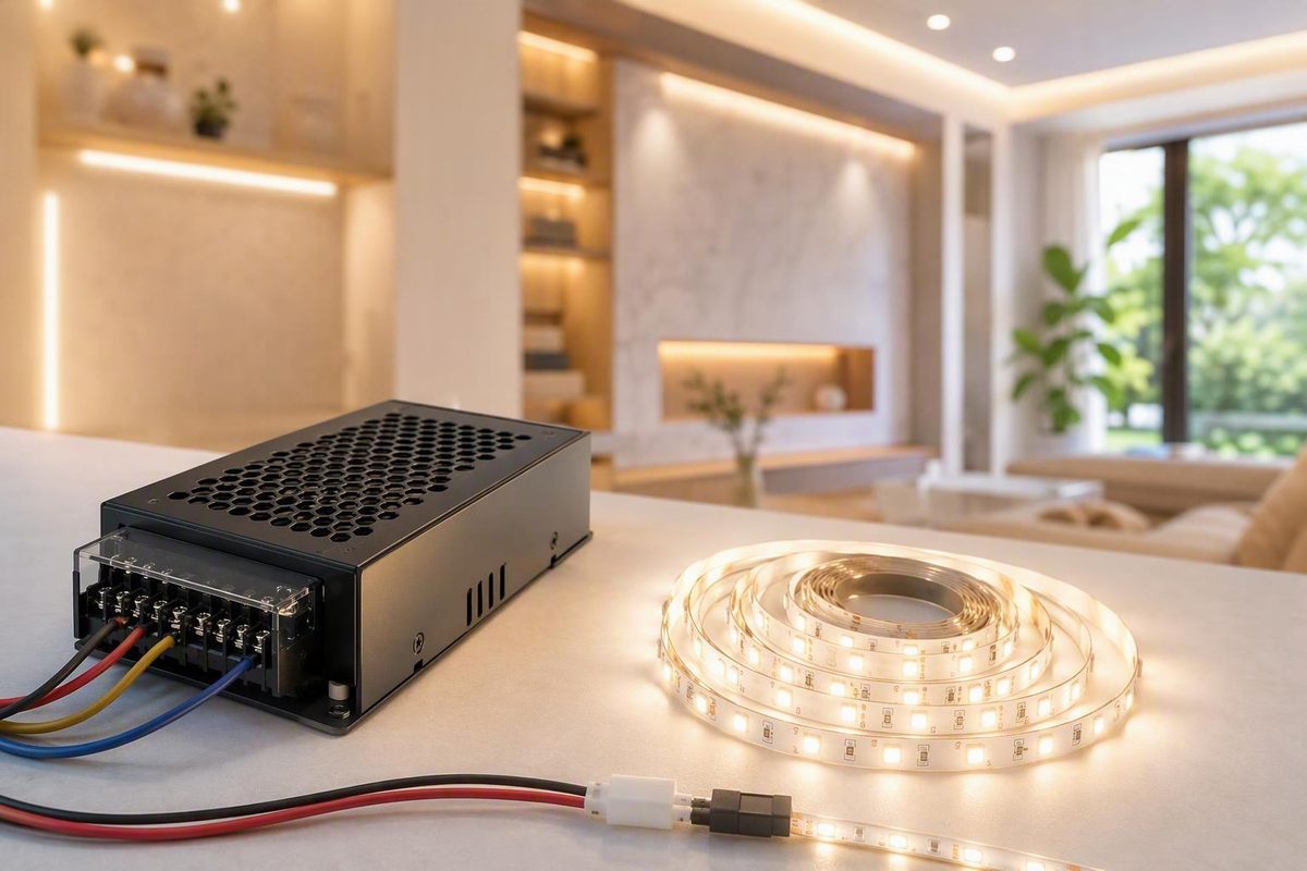
Connecting an LED strip to a power supply becomes straightforward once every part is treated as one system. Use this sequence:
- Match the strip’s rated DC voltage.
- Calculate the wattage of every installed section.
- Choose a compatible supply with reasonable spare capacity.
- Confirm that the controller, connectors, conductors, and distribution points can carry their respective current.
- Verify polarity before applying power.
This guide covers the low-voltage side of typical 5V, 12V, and 24V LED-strip installations. It does not explain AC line, neutral, protective-earth, electrical-panel, or exposed mains-terminal wiring. A plug-in AC-to-DC supply is often the practical DIY option. If a project requires permanent mains wiring, use a qualified electrician.
LED Lighting Zone publishes independent informational coverage of low-voltage strips, drivers, dimming, and fixture choices, as explained on its About page. Its editorial terms also place line-voltage and panel work outside the scope of its low-voltage articles.
Start Here: The Five Checks Before Connecting Anything
Do not choose a power supply from the strip’s appearance, reel length, or connector alone. First identify:
- Rated voltage: commonly 5V, 12V, or 24V DC.
- Power density: watts per meter or watts per foot.
- Installed length: the combined length of every section and branch.
- Strip type: single-color, tunable-white, analog RGB/RGBW, or addressable.
- Connection format: barrel plug, bare leads, exposed copper pads, multiconductor plug, or an existing controller.
Look for these details on the reel label, packaging, printed circuit markings, datasheet, manufacturer specifications, and controller documentation. If the sources conflict, stop and ask the manufacturer rather than guessing.
Identify the strip type
Strip type affects the conductor count, controller, connector, and wiring arrangement.
- Single-color analog strip: Normally has positive and negative connections. It may connect directly to a compatible constant-voltage supply if no dimming or smart control is required.
- Tunable-white strip: Uses separate channels to vary color temperature and generally needs a compatible controller.
- Analog RGB or RGBW strip: Uses a common conductor plus separate color channels. It requires a controller with the correct channel arrangement and adequate electrical capacity.
- Addressable strip: Contains control electronics and uses a specified data protocol. Voltage, data direction, connector orientation, logic requirements, and power-injection arrangements must follow the strip manufacturer’s diagram.
Do not identify a strip solely by counting its wires. Examine the pad labels and product documentation.
Identify the physical connection
A strip may have:
- a male or female barrel plug;
- bare positive and negative leads;
- a multiconductor controller plug;
- exposed copper pads at a cut point;
- or a controller already installed between the strip and its adapter.
The connection format determines which plug, splice, clip, or soldered lead is appropriate. Suppliers consequently list strip connectors, splices, power leads, barrel plugs, and adapters as separate accessory categories in catalogs such as this LED-strip cable and connector range.
A clip may match the strip width while missing the copper pads or using the wrong conductor arrangement.
Confirm the supply category
Most conventional low-voltage LED strips use a constant-voltage DC supply. A strip marked 12V DC expects a compatible 12V constant-voltage output; a 24V DC strip expects 24V DC.
A constant-current LED driver is a different product category. Do not substitute one merely because its label includes a current rating. Use the supply type specified by the strip manufacturer.
Pre-purchase checklist
| Item | What to confirm |
|---|---|
| Strip voltage | Exact rated DC voltage |
| Power density | Watts per meter or foot |
| Total length | Every section and branch |
| Maximum run | Manufacturer-approved uninterrupted run and feed arrangement |
| Strip type | Single-color, tunable-white, RGB, RGBW, or addressable |
| Controller | Protocol, voltage range, channels, and current limits |
| Connector | Width, pad count, layout, polarity, gender, dimensions, and current rating |
| Environment | Indoor, damp, outdoor, heat-exposed, or water-adjacent |
| Supply location | Product-approved temperature, ventilation, environmental protection, and access |
| Mounting method | Surface or channel compatible with the strip’s instructions |
Completing this checklist prevents a common mismatch: a supply that has enough watts but cannot correctly operate the controller, connector, or strip.
Match the Strip and Supply Voltage Exactly
The central rule is:
A 5V strip needs a 5V DC output, a 12V strip needs a 12V DC output, and a 24V strip needs a 24V DC output.
Enough watts do not compensate for the wrong voltage.
A power-supply label commonly shows an AC input and a DC output. The input may list a range of household AC voltages, while the output lists 12V DC or 24V DC. Compare the strip rating with the DC output, not the AC input.
What happens when the voltage is wrong?
An output above the strip’s rated voltage can cause excessive heating and rapid component failure. In particular, a 12V strip connected to a 24V supply may overheat and fail quickly, while a 24V strip on 12V may be dim or may not operate correctly, according to this 12V-versus-24V technical guide.
If excessive voltage has been applied, disconnect the strip immediately. Do not repeatedly energize it to see whether it recovers; inspect the affected strip, controller, and connectors before using the system again.
More available amps are not the same as more voltage
A supply can generally offer more current or wattage capacity than the strip requires when:
- its output voltage is correct;
- it is the required supply type;
- its output is compatible with the controller and strip;
- and all manufacturer operating instructions are followed.
The rating identifies the supply’s available output capacity.
That does not make downstream ratings optional. The controller, terminals, connectors, conductors, and distribution hardware must still be suitable for the current each one carries.
Comparing 12V and 24V at equal power
Electrical power is:
P = V × I
Therefore:
I = P ÷ V
For an equal 48W load:
48W ÷ 12V = 4A
48W ÷ 24V = 2A
The 24V version draws half the current. Lower current can reduce resistance-related voltage loss in equivalent conductors and connections. These calculations and their implications for voltage drop are also illustrated in Waveform Lighting’s 12V and 24V comparison.
This does not mean that 24V is automatically brighter, always more efficient, or universally compatible with thinner conductors. Brightness, power density, conductor selection, cut spacing, and maximum run remain product-specific.
A 12V system may be practical when it must integrate with existing 12V equipment or when the chosen strip offers shorter cut increments. A 24V system can simplify voltage-drop management over longer distances. The selected strip’s datasheet remains controlling.
Calculate the Required Power-Supply Wattage and Current
After identifying the voltage, calculate the complete connected load.
Step 1: Calculate nominal strip wattage
Use:
Nominal strip watts = watts per unit length × installed length
For a 5-meter strip rated at 12W per meter:
12W/m × 5m = 60W
The nominal strip load is 60W.
If the installation has several sections, add them all:
Total nominal watts =
Branch A watts + Branch B watts + Branch C watts + ...
Include every section that can operate simultaneously. Also include controller or accessory consumption when the relevant manufacturer says it must be counted.
Use the documented power density for the actual strip. Do not combine optimistic marketplace figures, assumptions about partially used reels, or specifications borrowed from a visually similar product. LED density, channel configuration, and operating mode can change the load.
Step 2: Allow reasonable spare capacity
Approximately 20% spare capacity is common planning guidance, not a universal electrical-code rule or a substitute for the supply manufacturer’s loading instructions.
Using that convention:
60W × 1.2 = 72W
The selected supply should therefore provide at least 72W at the strip’s exact voltage. If standard choices are 60W, 75W, and 100W, the 75W or 100W model may be considered, subject to its operating conditions and the ratings of the rest of the system.
A related “80% loading” expression is:
Required supply rating = nominal load ÷ 0.8
For the same nominal load:
60W ÷ 0.8 = 75W
Adding 20% gives 72W, while limiting the nominal load to 80% of the supply rating gives 75W. They are close but not identical. Both are planning conventions; follow any product-specific loading, temperature-derating, or minimum-capacity instructions instead. The 60W-to-72W example is presented as a recommendation in this LED-strip power-supply guide.
Step 3: Convert watts to current
Use:
Current in amps = watts ÷ volts
For a 60W load:
60W ÷ 12V = 5A
60W ÷ 24V = 2.5A
For a branched 12V system:
Branch A: 24W ÷ 12V = 2A
Branch B: 18W ÷ 12V = 1.5A
Branch C: 18W ÷ 12V = 1.5A

Total current: 5A
The supply and main distribution path must support the total current. Each branch conductor and connector must support its branch current.
The supply is only one limit
A 100W supply does not turn every downstream component into a 100W component. Check:
- the supply’s continuous output rating;
- the controller’s input and output ratings;
- total controller current;
- per-channel current;
- connector and terminal ratings;
- branch current;
- conductor distance and voltage drop;
- strip-trace limits;
- maximum permitted run;
- and approved feed or injection arrangements.
Do not select wire gauge from strip voltage alone. Selection requires the calculated current, one-way distance, allowable voltage drop, routing, ambient conditions, termination method, product instructions, and applicable installation requirements.
Connect the Low-Voltage DC Side: V+ to Positive and V− to Negative
For a basic single-color strip using a compatible plug-in supply, the path is:
Household receptacle
        │
        ▼
Compatible plug-in AC-to-DC supply
        │
        ├── DC positive (+ / V+) ──► Strip positive (+)
        │
        └── DC negative (− / V−) ──► Strip negative (−)
The DIY connection covered here begins at the supply’s documented low-voltage DC output.
Do not connect a 5V, 12V, or 24V DC strip directly to household AC. Low-voltage strips require a compatible AC-to-DC supply, and vendor installation guidance explicitly distinguishes them from direct 110V or 220V outlet loads in this multiple-strip power guide.
Using a documented, touch-safe DC terminal output
Some products provide low-voltage output terminals marked V+ and V−. Use the following procedure only when those terminals are documented for user access and can be reached without opening an enclosure or coming near exposed AC-input parts.
If the product has exposed line-voltage terminals, an open mains compartment, or unclear separation between its input and output areas, do not proceed. Have the equipment enclosed and commissioned by a qualified electrician or choose a plug-in supply with a touch-safe low-voltage connector.
For an appropriate DC output:
- Unplug or otherwise disconnect the supply from power.
- Identify the terminals specifically documented as the DC output.
- Verify the strip’s positive and negative conductors.
- Loosen the designated
V+andV−terminals. - Insert the prepared conductors fully.
- Tighten the terminals according to the manufacturer’s instructions.
- Check that no loose strands can touch an adjacent terminal.
- Tug gently to confirm that the conductors are mechanically secure.
- Insulate and strain-relieve the low-voltage connection before testing.
This sequence is consistent with published low-voltage guidance for connecting verified positive and negative leads to V+ and V−; it must not be applied to an AC-input terminal area.
Verify polarity instead of trusting wire colors
Do not assume red is positive or black is negative. Previous splices, nonstandard harnesses, and manufacturing choices can make colors unreliable.
Verify polarity from:
+,−,V+, orV−labels;- markings beside the strip’s copper pads;
- the power-supply label;
- connector documentation;
- the controller diagram;
- or a correctly used multimeter on the low-voltage output.
Disconnect power before correcting it.
Choose the right physical connection
Matching barrel connector: Confirm plug dimensions, gender, polarity, voltage, and current rating.
Supply DC plug ──► Matching strip or controller socket
Attached leads and a splice: Join verified positive and negative conductors with a low-voltage splice suitable for the conductor size, current, and environment.
Supply + ── splice ── Strip +
Supply − ── splice ── Strip −
Solderless strip connector: Match the strip width, pad count, pad position, polarity, coating thickness, and expected current.
Soldered leads: Solder conductors only to designated pads and only where the strip manufacturer permits it. Insulate and strain-relieve the finished connection.
Neither soldering nor a clip connector is universally superior. Either method must be secure, compatible, and appropriately rated.
Connecting a cut strip
Cut only at designated cut marks. Cutting elsewhere can interrupt the internal circuit and leave part of the strip unusable, one of the installation errors identified in Flexfire LEDs’ guide to common LED-strip mistakes.
After cutting:
- Expose the pads only as directed by the manufacturer.
- Identify every pad label.
- Align the connector or leads with the correct pads.
- Confirm the connector matches the strip width and conductor count.
- Check polarity and channel order.
- Confirm that the connection can carry the branch current.
- Restore any environmental sealing required by the product instructions.
Commission the low-voltage connection
Before permanent mounting:
- Keep power disconnected while inspecting the connections.
- Remove loose strands and insulate exposed conductors.
- Recheck output voltage and polarity.
- Energize the system briefly under supervision.
- Confirm normal brightness, color response, and controller operation.
- Watch for flicker, shutdown, odor, or unusual localized heating.
- Disconnect power and correct any problem before mounting the strip.
A brief sample test confirms basic operation. It does not replace a later test with the complete intended load.
Add the Controller in the Correct Place
The typical controlled system order is:
Compatible power-supply DC output
                │
                ▼
         Controller input
                │
                ▼
Controller output channels or data
                │
                ▼
             LED strip
A single-color strip may connect directly to a compatible supply when no dimming or smart control is needed. Adjustable systems require corresponding control hardware:
- a supported single-color dimmer;
- a tunable-white controller;
- an analog RGB or RGBW controller;
- or an addressable controller supporting the strip’s data protocol and electrical requirements.
Match all three components
The supply voltage must match:
- the strip’s rated voltage; and
- the controller’s permitted input range.
The controller output must also match the strip type. A two-wire single-color controller is not an RGB controller, and an analog RGB controller cannot be assumed to operate an addressable strip.
Typical conductor categories include:
- Single-color: normally two conductors.
- Tunable-white: a common conductor and separate white channels, or another documented arrangement.
- Analog RGB/RGBW: a common conductor and individual color channels.
- Addressable: power, ground, and one or more data or clock conductors, with protocol and direction defined by the manufacturer.
These are categories, not universal pinouts. Follow the exact pad labels and wiring diagram for the selected products.
Check controller current limits
A controller may specify:
- maximum total current;
- maximum current per channel;
- maximum power at a stated voltage;
- terminal-size limits;
- and temperature or enclosure conditions.
Every applicable limit matters. A larger power supply does not make an undersized controller suitable.
Include every strip zone attached to the controller when calculating the load. If zones can operate simultaneously, calculate for the documented maximum operating condition rather than assuming users will always select a dim setting. Practical installation guidance likewise calls for sizing both the supply and controller for the combined load in this LED power-connection overview.
Do not improvise multi-supply control wiring
Controllers, repeaters, amplifiers, and separately powered zones can require specific signal references, grounding arrangements, isolation, or power sequencing. Use a manufacturer-approved diagram for the exact products.
A supply advertised as “dimmable” is also not automatically compatible with every wall dimmer, low-voltage controller, or strip. Every component must specify a compatible method.
Power Multiple Strips and Long Runs Without Dim Ends
Multiple compatible constant-voltage strip sections can share one supply when:
- every section uses the correct voltage;
- the supply supports the combined load;
- the controller remains within its ratings;
- each branch conductor and connector carries only an acceptable current;
- and the strip manufacturer permits the feed arrangement.
Separate parallel positive-and-negative feeds from a distribution point are often preferable to one unrestricted end-to-end chain.
                    ┌── +/− feed ──► Strip A
Supply or controller├── +/− feed ──► Strip B
distribution point └── +/− feed ──► Strip C
Each branch receives the system voltage from the distribution point and is less dependent on current traveling through earlier strip sections.
What voltage drop means
Real conductors, connectors, and strip traces have resistance. When current flows, some voltage is lost before it reaches the remote load. Visible effects can include:
- a dim far end;
- uneven color on a multichannel strip;
- a remote branch that is dimmer than a nearby branch;
- or unstable behavior as load increases.
Voltage drop depends on:
- branch current;
- one-way feed length;
- conductor and connector resistance;
- strip power density;
- strip copper-trace design;
- supply placement;
- and feed layout.
At equal power, a 24V system’s lower current can reduce resistive loss, but it does not eliminate the need to plan the feed.
Four common feed layouts
1. End feed
Suitable for a short run within the strip manufacturer’s current and run-length limits.
Supply +/− ──► [================ Strip ================]
The farthest LEDs receive power through the longest section of strip trace.
2. Center feed
When permitted, a center feed shortens the maximum electrical path along the strip.
[========== Strip ==========] ◄── +/− ──► [========== Strip ==========]
                                      Feed
Treat the two sides as separate branches when calculating current.
3. Dual-end feed from one approved distribution design
Both feeds originate from the same compatible supply or approved controller/distribution arrangement.
                    ┌── feed A ──► [========== Strip ==========]
One approved source┤
                    └── feed B ───────────────────────────────►
Use dual-end feeding only when the strip and controller documentation permit it. Do not interpret this layout as permission to connect two independent supplies to one continuous strip.
4. Parallel branches or approved injection points
Larger installations can be divided into shorter fed sections:
Distribution ──► Strip section A
             ├─► Strip section B
             ├─► Strip section C
             └─► Approved injection point
It does not mean attaching another supply to the same conductors without an approved diagram.
Do not use universal run-length rules
Generalized figures such as 5 meters for 12V and 10 meters for 24V are not universal limits. Power density, copper thickness, LED arrangement, brightness, feed design, and acceptable voltage drop all affect the permitted run.
Follow the selected strip’s maximum-run, feed-spacing, and injection instructions. Two strips with the same nominal voltage can have very different limits.
Ways to address excessive drop may include:
- shortening the cable route;
- relocating the supply;
- selecting conductors from a current-and-distance calculation;
- dividing the load into parallel branches;
- center feeding;
- or using manufacturer-approved injection points.
When to use separate supplies
Separate supplies may make sense when:
- independent zones need separate control;
- the total load exceeds one supply’s capacity;
- distances make centralized distribution impractical;
- or the equipment manufacturer specifies separate power zones.
Keep the zones electrically separate unless an approved system diagram says otherwise. Equal voltage labels do not establish that two supply outputs may be connected together.
Test the System Before Permanent Installation
Test the complete intended load before removing adhesive backing, closing channels, or concealing low-voltage wiring.
Pre-installation test checklist
- Confirm the supply’s DC output voltage.
- Verify polarity at the supply, controller, connectors, and strip.
- Connect the complete intended load rather than a short sample.
- Test all controller channels and maximum intended brightness.
- Look for flicker or intermittent operation.
- Compare brightness at the near and far ends.
- Compare output among parallel branches.
- Check whether the supply repeatedly shuts down or enters protection.
- Inspect terminals, splices, connectors, controller outputs, and distribution points.
- Confirm insulation and strain relief.
- Verify that the planned supply location meets the product’s environmental, temperature, ventilation, and access instructions.
Testing the full installation before final mounting, including checks for brightness and flicker, is recommended in this large LED-installation guide.
Measure under load
An unloaded voltage measurement can confirm basic output, but it may not reveal cable drop, resistive connections, or behavior at full demand.
If a remote section is dim, measure:
- voltage at the supply output while the complete load operates;
- voltage at the beginning of the strip;
- voltage at the far end or affected branch;
- and, where appropriate, voltage across a suspected low-voltage connector.
A normal supply voltage combined with a substantially lower far-end voltage suggests loss in the feed, connections, or strip path. Treat these as diagnostic possibilities and compare the readings with the product documentation.
Use test equipment only within its stated rating and only on the low-voltage DC side covered here.
Look for abnormal heating
During a supervised test, inspect:
- screw terminals;
- barrel connectors;
- solderless clips;
- splices;
- controller terminals;
- distribution points;
- branch conductors;
- and the supply enclosure.
Some equipment may warm during normal use, but concentrated heat at a connector, softening insulation, discoloration, smoke, or a burning odor requires immediate disconnection. Investigate contact quality, terminal tightness, branch current, conductor suitability, and component ratings before applying power again.
Operate the supply only within its documented load, temperature, enclosure, ventilation, and environmental conditions. If the proposed location does not comply with those instructions or prevents required inspection and service, choose another location.
Protect the complete system from its environment
Also consider:
- connectors and splices;
- resealed cut ends;
- cable entries;
- controller and supply enclosures;
- mounting temperature;
- condensation exposure;
- and location-specific installation requirements.
Follow the ratings and installation instructions for every component. If the project exposes AC terminals or requires permanent mains wiring, stop at the low-voltage boundary and use qualified help.
Troubleshoot No Light, Flicker, Dimming, and Overheating
Disconnect power before tightening, moving, or opening low-voltage connections. Do not bypass protective functions or repeatedly energize equipment showing heat damage. Loose connections, inadequate supply capacity, voltage drop, and excessive run length are among the common causes identified in large-installation troubleshooting guidance.
| Symptom | Likely low-voltage causes | Verification steps | Safe next action |
|---|---|---|---|
| No light | Supply not energized; wrong DC output voltage; reversed polarity; connector missing the pads; controller not configured; invalid cut point | Measure DC output; compare voltage labels; verify polarity and pad contact; check controller setup | Disconnect power, correct the mismatch or connection, and retest briefly |
| Entire strip is dim | Undervoltage; inadequate supply capacity; cable drop; controller brightness limit; incorrect setting | Measure supply and strip-input voltage under full load; confirm calculated watts and current; review controller settings | Correct the supply or controller selection, shorten the feed, or redesign the branch |
| Far end is dim | Voltage drop along cable or strip traces; excessive run; resistive connector; poor feed layout | Compare voltage at the supply, strip input, and far end under load; inspect connectors and maximum-run instructions | Use a shorter calculated feed, parallel branch, center feed, or approved injection arrangement |
| Flicker | Loose connection; incompatible dimmer or controller; overload cycling; intermittent pad contact | Test at steady output; inspect connections with power off; measure voltage during the fault; check dimming compatibility | Repair the connection or replace the incompatible or undersized component |
| Wrong color or channel response | Reversed connector; channel-order mismatch; incorrect controller; data-direction or protocol error | Compare each pad and terminal with the manufacturer’s diagram; inspect direction markings | Reconnect according to the exact strip and controller documentation |
| Hot wire or connector | Excess current; unsuitable conductor; loose terminal; poor clip contact; overloaded branch; damaged connector | Disconnect immediately; inspect for discoloration or melting; calculate branch current; verify ratings | Replace damaged parts and correct the branch design before re-energizing |
| Supply repeatedly shuts down | Excessive total load; short circuit; polarity error; controller fault; protection activation | Disconnect branches for diagnosis; recalculate load; inspect for shorts; verify controller limits | Remove the fault or divide the load; do not defeat protective functions |
| 12V strip connected to 24V | The strip received excessive voltage and may be damaged | Disconnect immediately; inspect for odor, heat, discoloration, or failed sections | Do not repeatedly retest; replace damaged components and use a verified 12V supply |
| One branch does not work | Open splice; reversed branch polarity; failed connector; broken strip section | Compare voltage and polarity at both branch inputs; inspect distribution terminals and pad contact | Repair or replace the failed connection with power disconnected |
| Short sample works, full installation fails | Full-load demand exceeds capacity; voltage drop increases; controller or connector limit is exceeded | Test the calculated full load; measure voltage under load; compare all component ratings | Resize or divide the system rather than approving it from a sample test |
Stop troubleshooting and obtain qualified help if you find damaged insulation, melted connectors, smoke, a burning odor, moisture inside electrical equipment, exposed mains parts, or repeated unexplained protection trips.
The final sequence is simple: confirm the exact DC voltage, calculate the complete wattage and current, check the supply and controller ratings, verify V+ and V− polarity, and conduct a full-load test before permanent mounting.
Reliable LED-strip wiring is a whole-system exercise. The supply, controller, connectors, conductors, distribution points, and strip must all be compatible. Exposed mains, grounding decisions, panel work, and uncertain code requirements remain outside this low-voltage guide.
Frequently Asked Questions
Can I use a power supply with more amps than my LED strip needs?
Yes, generally. A supply may offer more current capacity than the strip’s calculated demand if its DC output voltage and supply type are correct.
For example, a strip calculated to draw 3A at 12V can normally operate from a compatible regulated 12V supply rated for 5A. The 5A rating is available capacity; it is not automatically forced through the strip.
The controller, connectors, conductors, and branches must still remain within their own ratings.
What happens if I connect a 12V LED strip to a 24V power supply?
The strip receives twice its rated voltage and may overheat or fail rapidly.
Disconnect it immediately and do not repeatedly switch it on. Inspect the strip, controller, and connectors for damage before reconnecting the system to a verified 12V DC supply.
Can I connect a 12V or 24V LED strip directly to a wall outlet?
No. A low-voltage 12V or 24V DC strip must not be connected directly to household AC.
Use a compatible AC-to-DC supply whose output voltage matches the strip and whose capacity supports the complete load. If the supply requires exposed line-voltage or permanent branch-circuit wiring, use a qualified electrician.
Can one power supply run multiple LED-strip sections?
Yes, if all sections use the same compatible constant-voltage output and the supply supports their combined load.
Add the wattage of every section that can operate simultaneously. Then check the controller’s total and per-channel limits, branch current, connector ratings, voltage drop, and strip-specific run instructions. Parallel feeds are often preferable to routing all current through one long daisy chain.
Why is the far end of my LED strip dimmer than the beginning?
A common cause is voltage drop through the feed cable, connectors, strip traces, or a combination of them. Measure voltage at the supply and at the far end while the complete strip operates.
If the far-end voltage is lower, inspect the connections and compare the installation with the strip manufacturer’s run and feed instructions. Depending on the approved design, the remedy may be a shorter cable route, properly selected conductors, parallel branches, center feeding, or manufacturer-approved power injection.