
Which Double-Sided Tape Works for Your LED Strip?
For a bare strip on smooth indoor metal or glass, a width-matched thin adhesive or modestly conformable acrylic tape is a reasonable starting point.
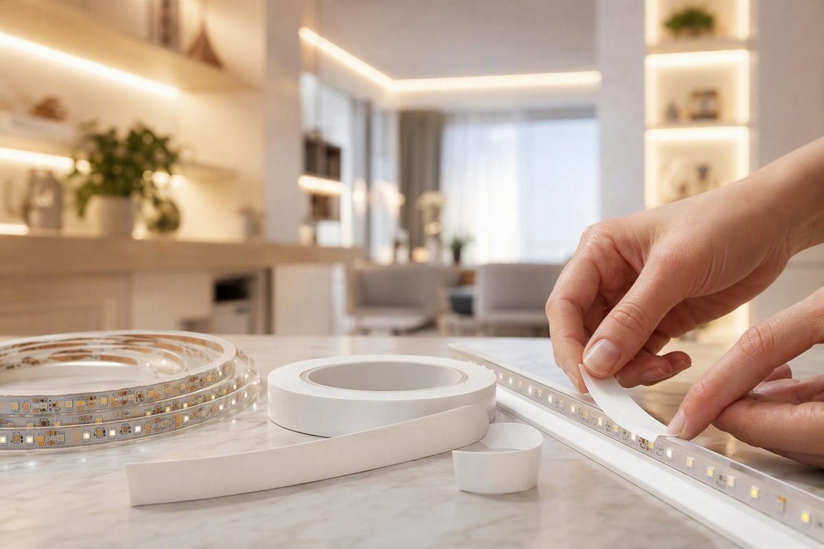
The right double-sided tape for an LED strip is not simply the roll with the strongest label. A dependable mount depends on the strip’s backing or waterproof jacket, actual width, mounting surface, texture, temperature, moisture exposure, orientation, vibration, desired permanence, and replacement needs.
Think of the bond as two separate interfaces:
- Tape to LED strip: The adhesive must grip the strip’s factory backing, flexible circuit, coating, or waterproof jacket.
- Tape to mounting surface: The opposite side must grip the metal, glass, paint, wood, plastic, or other substrate.
Either interface can fail while the other remains bonded. The strip may fall while the tape stays on the wall, or the tape may remain attached to the strip while pulling paint from the wall.
Quick selector: which mounting approach fits your LED strip?
Start by identifying the strip and installation conditions—not by choosing a brand or accepting labels such as heavy duty, permanent, or waterproof at face value.
| Strip construction | Mounting surface | Environment or orientation | Suitable starting approach | Backup support |
|---|---|---|---|---|
| Bare flexible strip | Smooth indoor aluminum or metal | Dry, stable, horizontal, vertical, or under-cabinet | Width-matched thin adhesive or modestly conformable tape compatible with both surfaces | Add clips at corners, cable exits, or points that tend to lift |
| Bare flexible strip | Clean glass | Indoor, smooth, and flat | Thin, low-profile adhesive compatible with glass and the strip backing | Test first; backup may be unnecessary for a short, lightly stressed run |
| Bare flexible strip | Sealed or painted wood | Indoor and slightly uneven | Width-matched acrylic foam tape after testing the finish | Use clips for long or difficult-to-replace runs |
| Bare flexible strip | Slightly uneven surface | Small gaps or mild vibration | Conformable double-sided acrylic foam tape | Use clips or a channel if irregularities are more than modest |
| Bare flexible strip | PP, PE, powder coating, or difficult plastic | Any orientation | Adhesive family intended for the exact low-surface-energy material, possibly with a compatible primer | Prefer clips, brackets, or a channel where reliability matters |
| Silicone-sleeved strip | Most surfaces | Indoor or sheltered | Confirmed silicone-compatible adhesive system after testing | Silicone clips, ties, press-fit mounting, or a retaining channel preferred |
| Any strip | Ceiling or other overhead surface | Downward-facing or highly stressed | Tape may position the strip | Add brackets, clips, or a channel system that positively captures the strip |
| Any strip | Humid, wet, or exposed location | Condensation, splash, weather, or thermal cycling | Exact tape model verified for those conditions | Use suitable mechanical retention and seal electrical joints separately |
| Any strip | Vehicle or machinery | Vibration and temperature changes | Conformable tape compatible with both materials | Add clips, ties, brackets, or a retaining channel |
| Any strip | Tight curves or corners | Continuous bend and peel stress | Avoid forcing the strip; use tape only if suitable for both surfaces | Reinforce turns or use a purpose-made corner arrangement |
| Long or high-output strip | Aluminum channel | Warm, vertical, or overhead | Compatible tape can position the strip inside the channel | The channel counts as backup only if it captures the strip or includes suitable retainers |
VHB means Very High Bond, but the name refers to a family of double-sided acrylic foam tapes rather than one interchangeable product. Different products are intended for different substrates, textures, temperatures, and joint conditions. The acronym and product distinctions are explained in ConRo’s VHB selection guide.
Before installing a full run:
- Find the complete model number of the proposed tape.
- Read its current technical data sheet and application instructions.
- Confirm compatibility with both the LED strip and the mounting substrate.
- Check application and long-term service-temperature limits.
- Note any primer, pressure, and bond-development requirements.
- Install a short representative sample in the real orientation.
- Test that sample under realistic heat, moisture, and movement.
Commercial selection guidance treats substrate energy, texture, temperature, joint mismatch, tape thickness, and environmental conditions as separate variables. It also recommends application-specific testing rather than relying on a family name alone (Strouse’s VHB tape selection guide).
There is therefore no defensible single ranking of the “strongest” or “best” double-sided tape for every LED installation. The available evidence does not provide standardized, independent comparisons across strip jackets, substrates, temperatures, orientations, bond areas, and service conditions.
Thin adhesive, tissue tape, or acrylic foam: understand the tradeoffs
Double-sided LED mounting products fall into several practical categories.
These products keep the strip close to the mounting surface and are generally positioned for smooth, flat surfaces that meet closely.
Double-sided acrylic foam tape has a thicker, conformable core. Products sold under the VHB name fall within this broad category. The foam can accommodate small gaps, slight surface mismatch, and modest irregularity. Its flexibility may also help when vibration or differential movement would stress a thin bond line.
A practical starting rule is:
- Choose thin tape when both surfaces are smooth, flat, clean, and closely matched, and a low profile matters.
- Consider acrylic foam tape for small gaps, slight unevenness, vibration, or dissimilar surfaces that do not remain perfectly aligned.
- Choose mechanical mounting when the substrate is rough, porous, weak, sharply curved, wet, hot, overhead, or difficult to bond.
Commercial LED tape guidance follows this general division, while also treating surface energy, temperature, humidity, load direction, and permanence as separate selection factors (Sunro LED’s adhesive-tape guide).
Why thicker is not automatically better
A thicker tape is useful only if it:
- Fits behind the strip without protruding.
- Contacts both surfaces adequately.
- Uses adhesive compatible with both materials.
- Tolerates the operating environment.
- Does not create an unwanted visual offset.
- Can be pressed uniformly over the full run.
Soft foam cannot compensate for loose paint, dust, oil, dampness, or a crumbling substrate. It may bridge shallow irregularities, but it cannot turn an unsound coating into a reliable mounting surface.
There is also an unresolved thermal tradeoff. Where thermal management matters, follow the strip and channel manufacturers’ instructions rather than assuming that every foam thickness is harmless.
Labels are not specifications
The words VHB, heavy duty, permanent, waterproof, and weather resistant do not establish suitability by themselves. Check:
- Exact adhesive formulation and product family
- Tape thickness
- Supported substrates
- Application-temperature range
- Long-term service-temperature range
- Moisture and UV suitability
- Surface-preparation requirements
- Required application pressure
- Bond-development period
- Removal method and likely surface damage
You may encounter 3M 4229P repeatedly in LED mounting listings. Treat it as an example of a commercially offered acrylic foam tape, not as a universal recommendation. Suitability still depends on the exact materials, environment, installation method, and current product documentation.
Match the tape to the strip width and construction
Measure the actual LED strip or channel with a ruler or caliper. Do not rely only on a nominal description such as “8 mm strip,” especially if the strip has a waterproof sleeve, reinforced edge, connector, or manufacturing tolerance that changes its effective width.
The tape should normally be close to the strip’s usable backing width. It should not:
- Protrude beyond the edges and collect dirt.
- Contact exposed copper pads.
- Cover cut marks or service points.
- Interfere with solder joints or clip connectors.
- Prevent a sleeved strip from seating in its clips or channel.
- Require such narrow trimming that the adhesive becomes uneven or damaged.
For a nominal 8 mm or 10 mm strip, start with a tape of approximately the corresponding width, but verify the flat, bondable area. Raised edges, jacket seams, or an uneven factory backing may make the usable area narrower than the strip’s overall width.
Examples of listed LED mounting tapes
The following details come from seller listings rather than independent performance tests. Availability, warranties, environmental claims, and specifications may change.
| Seller | Model or description | Listed width | Listed length | Stated application | Stated environment | Notable limitation |
|---|---|---|---|---|---|---|
| Armacost Lighting | 3M 4229P foam mounting tape | 8 mm; a 10 mm selection is also shown | The detailed 8 mm listing states 10 m | LED tape lights, channels, controllers, and power supplies | Seller describes it as weather resistant | Detailed dimensions apply only to the extracted 8 mm listing; no load or temperature data are provided |
| Diode LED | 3M 4229/4229P acrylic foam tape | 8 mm or 21 mm | Options show 100 ft, 4 ft, and 12 ft | Lighter-weight LED fixtures on flat, clean surfaces | Indoor only | The description also mentions a conflicting 9.5 ft sales length |
| Solid Apollo | 3M double-sided tape mainly for LED strips | 10 mm | Listed as both 150 ft and 50 m | Mainly 10 mm LED strips | Not stated | The length statements conflict, and no numeric thickness is supplied |
Armacost identifies the detailed 8 mm product as 3M 4229P measuring 10 m long, 8 mm wide, and 1.5 mm thick. Its page also presents an 8 mm/10 mm width choice, but the extracted listing does not provide equivalent dimensions for the 10 mm option.
Diode LED describes its 4229 tape as intended for lighter-weight fixtures on flat, clean indoor surfaces. That seller classification should not be transferred automatically to another product carrying a related model or family name.
Solid Apollo lists its 10 mm product as both 150 feet and 50 meters. Those values are not equivalent, so the page cannot support a definitive cost-per-foot calculation without clarification.
Bare strips and waterproof strips are different bonding jobs
A bare flexible strip usually presents a relatively flat backing, sometimes with factory-applied adhesive beneath a release liner. Replacement tape may bond to that backing if the materials and adhesive chemistries are compatible.
A strip enclosed in silicone tubing presents a different interface. The jacket can be smooth, flexible, and difficult for ordinary pressure-sensitive adhesive to wet and grip. Tape that works on a bare flexible circuit may release readily from a silicone sleeve.
Mounting a channel, controller, driver, or power supply is also different from mounting a flexible strip. Equipment may have:
- More weight and leverage
- A smaller or discontinuous bonding area
- Higher operating temperature
- Cable loads
- A rigid enclosure that transmits vibration
- Ventilation and service-access requirements
Do not infer that tape advertised for LED strips is automatically suitable for power equipment. Evaluate the item’s weight, operating conditions, bond area, orientation, cable strain, ventilation, and replacement needs separately.
Choose for the mounting surface, not just the LED strip
Adhesive must spread across a material closely enough to create intimate contact. Some materials permit that more readily than others, even when both look smooth.
This behavior is often described through surface energy. In plain language, higher-surface-energy materials tend to let a compatible adhesive spread more readily.
| Mounting substrate | Practical assessment | Preferred starting approach | Main cautions |
|---|---|---|---|
| Smooth aluminum or bare metal | Generally an easier starting surface for compatible acrylic adhesive | Thin tape for very flat surfaces; modest foam for small mismatch | Remove oil, oxidation, dust, and machining residue by an approved method |
| Glass | Smooth and nonporous, allowing close contact | Thin, transparent, or low-profile compatible adhesive | Cleaner residue, condensation, coatings, and appearance through the glass |
| Sealed or painted wood | Performance depends on coating, texture, and finish adhesion | Test thin or conformable tape according to surface condition | Strong tape may lift varnish, paint, or veneer during removal |
| Painted wall | Highly variable | Test first; consider clips or a reversibly mounted channel | The paint may detach from the wall even if the tape holds |
| Textured finish | Reduced real contact area | Conformable foam only for modest texture | Pronounced texture, porosity, or dusting favors mechanical mounting |
| Powder-coated metal | Performance varies with coating formulation and texture | Tape family confirmed for the exact coating | The metal beneath the coating does not determine adhesion |
| Common rigid plastics | Varies by resin, additives, and finish | Identify the plastic and confirm compatibility | PP and PE are commonly difficult; cleaners may also affect plastic |
| Silicone jacket | Difficult for ordinary pressure-sensitive tape | Tested silicone-compatible system | Mechanical retention is usually the conservative starting point |
Clean, smooth glass and metal are generally easier starting surfaces for compatible acrylic adhesives, but they do not guarantee success. Coatings, release agents, corrosion, fingerprints, and cleaner residue can still cause failure.
Painted walls and furniture finishes require particular caution. The limiting interface may be the paint’s grip on drywall or the finish’s grip on wood—not the tape’s grip on the finish.
Roughness reduces the area actually contacting the adhesive. Conformable foam may fill modest irregularities, but it cannot reliably bridge deep texture, open pores, loose fibers, chalking paint, or dusting masonry. When the substrate cannot provide a continuous, sound bond, use a suitably fixed mounting structure instead.
Low-surface-energy plastics may require a tape designed for the exact material or a compatible adhesion primer. A primer is not a universal repair: it must suit the plastic or coating, LED backing or jacket, selected adhesive, environment, and finished appearance.
Before full installation, test an inconspicuous area for:
- Adhesion
- Residue
- Discoloration
- Softening or swelling
- Paint or finish damage
- Visible primer staining
Follow the current tape and primer manufacturers’ compatibility, application, handling, ventilation, and disposal instructions. Supplier blogs can help narrow the options, but they are not substitutes for current model-specific technical and safety documentation.
Account for heat, humidity, weather, orientation, and movement
A tape that holds a short indoor strip on a horizontal shelf may not perform the same way on a ceiling, beside a shower, or in a vehicle. Evaluate each stressor separately.
LED heat and thermal cycling
LED strips warm during operation and cool after shutdown.
Verify both the application-temperature range and long-term service-temperature range for the exact tape. They are not necessarily the same. Also consider sunlight, enclosed cabinets, cooking appliances, vehicle interiors, and nearby machinery rather than evaluating only the strip’s heat.
Do not judge a new installation solely by initial stickiness. Allow the specified bond-development period, then screen a short test section through operating and cooling cycles appropriate to the installation.
Humidity
Painted drywall, wood products, and porous surfaces may also change with moisture.
For a bathroom or similarly humid area, account for condensation, cleaning, steam, and splash. Apply the tape only to a dry surface and avoid exposing the new bond to moisture before the specified dwell period ends.
Direct outdoor exposure
“Waterproof tape” does not make an LED installation weatherproof. Separate vulnerabilities include:
- Cut strip ends
- Soldered or clip connections
- Cable exits
- Seams and end caps
- The strip enclosure
- The mounting substrate
- Primer coverage
- Fastener penetrations
- Water trapped behind the strip or channel
Seller descriptions also conflict for related 4229 products. Diode LED labels its listed product indoor only, while Armacost markets its listing as weather resistant. Because those are seller classifications rather than standardized comparative results, obtain current documentation for the exact model instead of transferring environmental claims between listings.
For exposed outdoor runs, treat the adhesive as one part of the mounting assembly—not as proof that the electrical joints, strip enclosure, and supporting surface are protected.
Vertical shear
Long runs, warm surfaces, heavy sleeved strips, and unsupported lead wires increase the stress. Relieve cable tension and use clips or a suitable channel arrangement when sustained shear is significant.
Overhead peel risk
Commercial LED installation guidance recommends supplementing tape with channels or brackets for overhead and highly stressed installations (Sunro LED’s mounting guidance).
An open aluminum profile does not automatically provide positive retention. The channel itself must also be installed appropriately for its surface, orientation, and environment.
Corners and curves
Forcing it around a tight corner creates continuing peel stress, especially along the edge of the bend. Connectors and lead wires can add leverage.
Do not force a strip into a sharper bend than its manufacturer permits. Use a suitable connector, cut-and-join arrangement, corner profile, or gradual supported curve. Secure the lead separately so it does not pull on the adhesive.
Vehicles and machinery
Vehicles and machinery can combine vibration, dust, cleaners, temperature changes, and difficult plastics. Use a tape compatible with both surfaces and add an appropriate retaining method where movement is substantial.
A representative sample should reproduce the intended orientation and foreseeable vibration only after its full bond-development period. This is a screening test for obvious incompatibility, not a certification of long-term durability.
Why sagging affects the light
Sagging is not only cosmetic. It changes the strip’s distance and angle relative to the illuminated surface, potentially creating uneven brightness, visible LED points, or hotspots. Channels help keep strips straight, while clips can reinforce corners and sections that do not lie flat (The Hook Up’s LED installation guidance).
Do not treat seller holding-power figures as proven LED-specific capacities. Without standardized test methods, substrate details, bond area, temperature, load direction, dwell time, and appropriate design factors, those figures cannot establish suitability for a particular installation.
Install double-sided tape on a bare LED strip
This method applies to low-voltage bare LED strips when the selected tape is confirmed as compatible. Product-specific instructions take priority.
-
Disconnect power. Isolate the low-voltage supply before handling the strip, contacts, or connectors. Keep the work within the low-voltage system; panel and line-voltage work should be left to a qualified electrician, consistent with the publisher’s stated electrical-work boundary.
-
Confirm compatibility and width. Verify the exact tape model against the strip backing, substrate, temperature, moisture, and orientation. Make sure it fits within the usable bonding width.
-
Test a hidden area. Check for adhesion, residue, discoloration, softening, or finish damage. If possible, test a spare strip segment as well.
-
Inspect both bonding surfaces. Look for dust, grease, fingerprints, loose paint, oxidation, wax, silicone polish, moisture, factory adhesive residue, and raised seams.
-
Clean by a material-compatible method. Isopropyl alcohol is commonly recommended in commercial tape guidance, but first confirm that it will not damage paint, plastic, coatings, printed markings, or the strip backing.
-
Let both surfaces dry fully. Do not trap cleaner or moisture beneath the tape.
-
Avoid touching the cleaned areas. Handle the tape by its liner or edges to reduce contamination.
-
Apply the tape to the first surface without stretching it. Stretching may encourage later contraction and edge lift. Avoid wrinkles, bubbles, and gaps.
-
Press the tape evenly onto the first surface. Pressure-sensitive adhesive requires firm, uniform contact. Use a suitable roller or smooth pressure tool if permitted, without applying damaging point loads to LED components.
-
Remove the release liner carefully. Avoid lifting or disturbing the tape as the liner comes away.
-
Position the strip once. Align the run before making contact. Repeated lifting and repositioning can contaminate the adhesive and reduce reliability.
-
Press the full run firmly. Apply uniform pressure rather than pressing only between LEDs. Avoid damaging exposed joints or components.
-
Relieve cable and corner tension. Secure lead wires separately, avoid forced bends, and reinforce corners or lifted points with suitable clips.
-
Leave the bond unloaded for the specified dwell period. Initial tack is not full developed bond strength. Commercial LED guidance gives a range of approximately 24 to 72 hours, depending on the tape and conditions, so the exact product instructions control (HitLights’ mounting-tape application guide).
-
Delay environmental stress. Avoid full operating heat, vibration, moisture, cable loading, and aggressive cleaning until the specified bond-development period has elapsed.
Do not attempt to bridge dust, grease, loose paint, uncured coatings, dampness, or pronounced texture by selecting a “stronger” tape. The adhesive can bond only to the material it actually contacts. If that material is contamination or a weak coating, the assembly remains weak.
Mount silicone-covered and waterproof LED strips
Silicone tubing is a difficult bonding surface, and ordinary double-sided foam tape should not be assumed to hold reliably.
An informal forum test reported that 3M double-stick foam tape released readily from one waterproof flex-strip sleeve. Participants suggested clamps, ties, or press-fit mounting where retention mattered. The report was anecdotal and product-specific rather than controlled research, so it does not establish that every tape will fail on every silicone jacket (Adafruit’s waterproof-strip mounting discussion).
A commercial LED vendor recommends a different procedure: clean the silicone, apply 3M Primer 94, wait 10 minutes, apply 3M VHB 4229P, press for approximately 30 seconds, and wait 24 hours before mounting. This is vendor guidance without controlled long-term load, temperature, or environmental data (Ledbe’s silicone-tube adhesive procedure).
These reports do not prove opposite universal rules. They concern different products, preparations, and conditions. Together, they show why silicone requires a material-specific approach.
Route 1: mechanical retention
This is the conservative starting point. Depending on the strip and installation, suitable options may include:
- Clips intended for the sleeved strip
- Ties used with appropriate mounts
- A press-fit holder
- Brackets supplied or approved for the strip
- A channel that captures the strip or uses positive retainers
The mounting hardware, channel, and fasteners must suit the substrate and environment. A plain open channel that still relies entirely on tape does not become mechanical retention merely because it is made from aluminum.
Mechanical retention is particularly appropriate for long or heavy sleeved runs, warm locations, vibration-prone installations, frequently cleaned areas, and downward-facing arrangements.
Route 2: a confirmed adhesive system
If adhesive mounting is necessary:
- Identify the exact jacket material rather than relying only on the word waterproof.
- Identify the exact tape and primer models.
- Obtain current compatibility, application, and safety instructions.
- Test the cleaning method on both the jacket and substrate.
- Follow the specified primer coverage, waiting time, application temperature, and handling requirements.
- Apply the tape with the prescribed pressure.
- Observe the complete bond-development period.
- Test a short section under representative heat, moisture, orientation, and movement.
- Add positive retention where release would be difficult to correct.
Do not interpret the Primer 94 and 4229P procedure as proof of a permanent, universally outdoor-safe, or waterproof bond. Even if the tape adheres to the jacket, the complete installation still includes cut ends, seams, connectors, cable exits, end caps, the substrate, and any mounting penetrations.
Know when to use clips or an aluminum channel—and how to troubleshoot failure
Tape is low-profile and quick to apply, but it is not always the simplest system over the full life of an installation.
| Mounting method | Appearance | Installation effort | Straightness | Serviceability | Surface-damage risk | Environmental reliability | Mechanical retention |
|---|---|---|---|---|---|---|---|
| Tape only | Very discreet | Low initially | Depends on alignment | Often poor with permanent tape | May remove paint or leave residue | Highly dependent on materials and preparation | None beyond the adhesive bond |
| Clips | Visible at intervals | Moderate | Good with suitable spacing | Often good | Screw holes or clip marks may remain | Less dependent on continuous adhesive contact | Positive retention at clip locations |
| Open aluminum channel | Clean, finished appearance | Higher initially | Excellent | Usually good if accessible | Depends on how the channel is fixed | Provides a controlled mounting surface | Does not necessarily retain the strip after adhesive failure |
| Capturing channel or channel with retainers | Clean; may accept a diffuser | Higher initially | Excellent | Depends on cover and retainer design | Depends on channel attachment | Better suited to demanding orientations | Positive retention when the design captures the strip |
| Hybrid tape plus clips or retaining channel | Usually neat | Moderate to high | Excellent | Varies with tape choice | Combines adhesive and hardware effects | Strong practical option for demanding runs | Tape positions; hardware retains |
An aluminum channel can keep the strip straight, conceal the flexible circuit, and support a diffuser. It may also assist heat dissipation, although the supplied evidence does not quantify the improvement for each strip, tape thickness, and channel design.
In a hybrid arrangement:
- Tape positions the strip and can reduce movement.
- Clips or positive-retention features keep the strip from releasing if the adhesive fails.
- Channel geometry and diffusers control alignment and appearance.
- Removable covers or clips can improve replacement access.
Troubleshooting peeling, sliding, and sagging
| Symptom | Likely causes | Remedy |
|---|---|---|
| Edge lifts soon after installation | Contamination, insufficient pressure, touched adhesive, or incompatible tape | Remove the affected tape, clean by an approved method, and reapply with uniform pressure |
| Corner lifts | Bend is too tight, strip is trying to straighten, or cable tension is pulling the run | Reduce bend stress, secure the lead separately, and add corner support |
| Strip sags | Unsuitable tape, uneven surface, insufficient contact, or premature loading | Replace the tape if appropriate and add clips or a retaining channel |
| Tape stays on the wall but releases from the strip | Strip backing or jacket is incompatible or contaminated | Identify the strip material and use a compatible adhesive system or mechanical retention |
| Tape stays on the strip but pulls from the wall | Weak paint, dust, moisture, texture, or substrate incompatibility | Stop relying on the weak coating and use a suitably mounted support |
| Silicone-covered strip releases | Material incompatibility or inadequate preparation | Use sleeve-compatible clips or a tested primer-and-tape system |
| Strip slides slowly downward | Heat, sustained shear, excessive weight, or inadequate dwell | Remove the load, verify temperature suitability, and add retention |
| Random sections release | Variable pressure, texture, damp patches, weak coating, or inconsistent cleaning | Inspect the substrate section by section rather than patching over an unsound surface |
| Adhesive softens or creeps near LEDs | Tape may be unsuitable for the service temperature | Verify actual conditions and select an appropriate system |
| Light pattern becomes uneven | Sagging changed the strip’s angle or distance | Restore alignment with clips or a straight channel |
Validate a small area before committing
Use a representative screening test:
- Prepare a sample of the real strip and substrate.
- Use the exact cleaner, primer, tape, pressure, and installation temperature planned for the job.
- Observe the product-specific bond-development period.
- Mount the sample in the intended orientation.
- Operate the LEDs through heating and cooling cycles appropriate to the expected use.
- Reproduce foreseeable humidity or vibration without introducing an electrical hazard.
- Inspect the tape-to-strip and tape-to-substrate interfaces separately.
- Look for edge peel, bubbles, creep, softening, discoloration, coating lift, or jacket damage.
- Choose a test duration proportionate to the consequences of failure.
This can reveal obvious incompatibility, but it does not certify unlimited service life. Critical applications require manufacturer guidance or appropriately qualified design assistance.
Plan removal before choosing permanent tape
High-bond tape may:
- Pull paint from drywall
- Lift clear coat or furniture finish
- Leave adhesive residue
- Tear the flexible LED circuit
- Separate a waterproof jacket
- Deform plastic trim
- Make channel or strip replacement difficult
If the installation is temporary, rented, likely to be upgraded, or located on a valuable finish, prioritize removable clips, a serviceable channel, or another mounting structure that does not depend on permanent adhesive.
Disconnect power before removal. Follow the tape, strip, and substrate manufacturers’ removal instructions rather than assuming that heat, solvent, scraping, or prying is safe. A method suitable for glass may damage plastic or paint.
Pre-installation checklist
Before buying or applying double-sided tape, confirm:
- [ ] Actual strip width
- [ ] Usable flat bonding width
- [ ] Bare backing, coating, or jacket material
- [ ] Exact mounting substrate
- [ ] Paint, finish, or powder-coat condition
- [ ] Surface smoothness, porosity, dusting, and cleanliness
- [ ] Indoor, humid, wet, or outdoor environment
- [ ] Horizontal, vertical, overhead, corner, or curved orientation
- [ ] Expected vibration and cable strain
- [ ] Application and service temperatures
- [ ] Exact tape model and thickness
- [ ] Compatibility at both adhesive interfaces
- [ ] Required cleaner or primer
- [ ] Application pressure and bond-development time
- [ ] Desired permanence
- [ ] Removal and replacement access
- [ ] Consequences of detachment
- [ ] Positive mechanical retention where needed
- [ ] Current technical data and application instructions
- [ ] Successful representative screening test
Frequently asked questions
What is the best double-sided tape for LED strip lights?
There is no single best tape for every LED strip. For a bare strip on smooth indoor metal or glass, a width-matched thin adhesive or modestly conformable acrylic tape is a reasonable starting point. Slight unevenness may favor acrylic foam. Low-surface-energy plastics and silicone jackets may require a specialized adhesive system.
Overhead, wet, hot, curved, long, or vibration-prone installations should use clips or a channel with positive-retention features rather than relying on tape alone. Choose the exact tape model only after checking both bonded materials, surface texture, environment, orientation, permanence, and application instructions.
How wide should the tape be for an 8 mm or 10 mm LED strip?
Match the tape closely to the strip’s actual usable backing width. An 8 mm strip commonly starts with approximately 8 mm tape, while a 10 mm strip commonly starts with approximately 10 mm tape, but the strip should be measured before ordering. Armacost, for example, lists both 8 mm and 10 mm mounting-tape selections (Armacost’s LED mounting adhesive listing).
Keep the adhesive inside the strip edges and away from exposed pads, connectors, cut points, and raised jacket seams. A sleeved strip may have a different usable bonding width from the flexible circuit inside it.
How long should LED mounting tape develop its bond before I turn on or load the strip?
Follow the exact tape manufacturer’s instructions. Commercial LED guidance describes approximately 24 to 72 hours for maximum bond development, depending on the product and conditions.
Initial tack does not mean the bond is fully developed. During the specified dwell period, avoid full operating heat, sustained load, vibration, moisture, and cable tension.
Will ordinary double-sided tape stick to a silicone-covered waterproof LED strip?
It may develop temporary adhesion in some combinations, but it should not be assumed to hold reliably. Silicone is difficult to bond, and results vary with jacket formulation, tape chemistry, contamination, preparation, heat, humidity, and load. Informal testing has produced mixed, product-specific results rather than a universal rule (Adafruit’s waterproof-strip discussion).
The conservative solution is compatible clips, ties, press-fit retention, or a channel that captures the strip. An adhesive route requires a confirmed material-compatible system, current primer and tape instructions, and representative testing.
Can LED strip mounting tape be removed without damaging paint?
Not reliably. Strong permanent or semi-permanent tape may remove paint, lift a finish, leave residue, or damage the strip. Commercial mounting guidance expressly warns that removal may damage the mounted surface (HitLights’ tape guidance).
For painted walls or valuable finishes, test an inconspicuous area first and consider a replaceable channel or removable mounting method. Before removal, disconnect power and follow product-specific instructions.
The dependable choice is not the tape with the most forceful marketing. Measure the strip, identify its backing or jacket, inspect the substrate, and account for heat, moisture, orientation, vibration, and future removal. Prepare both surfaces carefully, apply uniform pressure, allow the specified bond-development period, and validate a short section under realistic conditions. Where detachment matters, use compatible tape for positioning and a properly designed clip or retaining channel for long-term support.