
LED Light Connectors Can Look Right but Not Work
Even with the same contact count, connectors can differ in PCB width, pad geometry, wire acceptance, polarity, coating clearance and ratings.
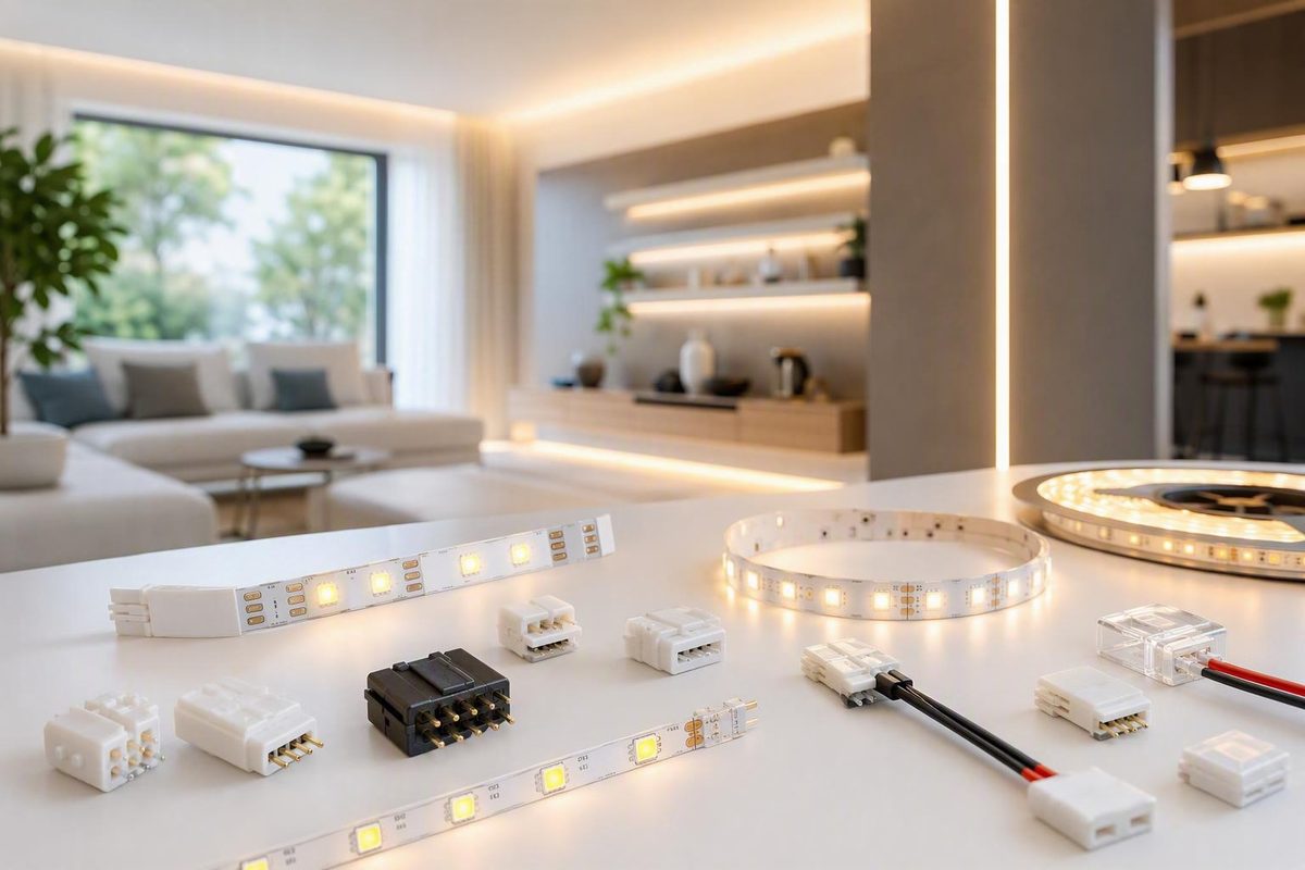
Choosing LED light connectors by pin count alone is an easy way to buy a part that looks right but does not work. Compatibility also depends on the strip’s electrical architecture, operating voltage, pad functions, PCB width, contact spacing, thickness, coating, wire fit, load, controller interface, and installation environment.
This guide covers connectors for flexible, low-voltage LED strip lights. It does not cover automotive connectors, fixture plugs, board-level components, or proprietary line-voltage strip systems except to explain why those systems require separate treatment.
What counts as an LED strip-light connector?
For this guide, an LED strip-light connector creates an electrical path between a flexible strip and another part of its low-voltage lighting system. It normally transfers power and may also carry analog color channels, tunable-white channels, digital data, or a clock signal.
The three broad categories are:
- Strip-to-strip connectors: Join two compatible cut sections directly.
- Strip-to-wire connectors: Connect a strip to cable leading to a power supply, controller, or another strip.
- Wire-to-wire connectors: Splice cable conductors without clamping directly onto the LED strip.
Common forms include straight or gapless couplers, wired jumpers, corner connectors, T-connectors, splitters, pigtails, DC barrel adapters, screw-terminal adapters, and power-input leads. Retail collections often place these beside wire, dimmers, controllers, and other accessories, so identify the connection job before searching broadly for “LED light connectors.” One current collection, for example, mixes solderless connectors with DC adapters, wire, dimmers, and controllers in the same product category.
| Installation job | Usually appropriate format | What to verify |
|---|---|---|
| Join two adjacent cut sections | Strip-to-strip straight coupler | Architecture, width, pad order, alignment, documented rating |
| Bridge a cabinet gap | Wired jumper or two strip-to-wire ends | Wire fit, polarity, channel order, routing, strain relief |
| Turn around a cabinet corner | Rigid corner connector or short wired jumper | Actual angle, available space, pad orientation |
| Connect a strip to a controller | Strip-to-wire connector or compatible pigtail | Controller terminal order, conductor count, voltage |
| Extend an existing cable | Wire-to-wire splice | Accepted wire, electrical rating, enclosure needs |
| Create parallel branches | T-connector, splitter, or distribution block | Combined load, branch design, power-system capacity |
A straight coupler is compact but requires both strips to meet squarely with all pads aligned. A wired jumper takes more room but can cross an unlit gap, accommodate an offset, or route around an obstruction. A rigid corner changes direction without folding the strip sharply. A splitter creates branches; it does not increase the documented capacity of the connector, cable, controller, or power supply.
Product names are not consistent enough to replace inspection. “Two-pin connector” might describe a single-color strip clip, a cable splice, a DC input component, or a system-specific line-voltage pin. Before shopping, identify what must connect at both ends: strip to strip, strip to wire, or wire to wire.
Identify the LED strip before choosing a connector
Do not begin with a connector listing. Begin with the strip and record its specifications.
Use this workflow:
- Determine whether the strip is analog or addressable.
- Read its rated operating voltage.
- Record every label printed beside the copper pads.
- Count the independent electrical connections.
- Measure the flexible PCB width.
- Inspect pad dimensions, spacing, and position.
- Note the strip’s thickness and any coating, sleeve, or encapsulation.
- Locate the manufacturer-designated cut marks.
- For addressable strips, identify signal direction and controller requirements.
- Compare your findings with the strip and connector manufacturers’ diagrams.
Typical conductor conventions can narrow the search, but they do not prove compatibility. Two connections commonly serve single-color strips; three may serve tunable-white or some addressable designs; four commonly serve RGB or certain addressable designs; five commonly serve RGBW; and six commonly serve RGBCCT. Addressable strips can use the same conductor count for different signal functions, so exact pad labels remain controlling as this connector-selection guide explains.
| Strip system | Typical pad labels | Typical conductor count | Checks that remain mandatory | Common mismatch risk |
|---|---|---|---|---|
| Single-color analog | + and -, or V+ and V- |
2 | Voltage, polarity, width, pad geometry, load | Reversed polarity or wrong PCB width |
| Tunable white/CCT | V+, WW, CW or equivalent |
3 | Common arrangement and controller order | Confusing it with a three-wire addressable strip |
| RGB analog | V+, R, G, B or equivalent |
4 | Common terminal and exact color order | Physical fit with swapped channels |
| RGBW analog | V+, R, G, B, W |
5 | Pad sequence, width, controller interface | Open or incorrectly assigned white channel |
| RGBCCT analog | Common/power plus RGB, warm-white, and cool-white channels | 6 | Exact labels and controller order | Assuming every six-contact layout is identical |
| Addressable, data only | Power, ground, and data labels such as 5V, DIN, GND |
Often 3 | Voltage, pinout, controller, direction | Treating it as analog CCT |
| Addressable with clock or auxiliary signal | Power, ground, data, and clock/backup labels | Often 4 | Exact signal functions and direction | Treating it as analog RGB |
| COB strip | Varies | Varies | Encapsulation, thickness, pad access, clearance | Assuming an SMD connector fits because width matches |
Pin count is a filter, not proof
A three-conductor CCT strip may use one common supply connection and two analog white channels. A three-conductor addressable strip may use power, data, and ground. The copper-pad count can match even though the required controller, pinout, and orientation do not.
The same issue occurs with four-conductor products. An analog RGB strip commonly uses a shared terminal plus red, green, and blue channels. An addressable design may instead use power, ground, data, and clock or another signal arrangement. A four-contact clip does not convert one architecture into the other.
Read the pad labels rather than relying on connector color or pin count. If the labels are missing, obscured, or unclear, find the strip manufacturer’s wiring diagram before buying or cutting anything.
Measure the strip correctly
Common retail connector sizes include nominal 8 mm, 10 mm, and 12 mm PCB widths, with different widths and contact counts sold for different strip families. Measure across the flexible PCB itself, not an aluminum channel, diffuser, removable sleeve, or unrelated housing.
Width is only the first dimensional check. Each metal contact must land squarely on its corresponding copper pad. A nominally correct connector can still fail to fit when:
- Pad spacing differs.
- Pads are unusually short or narrow.
- The strip is too thick for the connector throat.
- Components sit too close to the cut line.
- COB encapsulation blocks the contacts.
- A coating prevents metal-to-copper contact.
- Side guides position the PCB away from the contacts.
Verify the operating voltage from the strip label or its manufacturer’s documentation. The power supply’s DC output must match that rated voltage; a connector advertised for several voltages does not make differently rated strips and supplies interchangeable according to low-voltage strip wiring guidance.
Choose the connector format for the physical layout
After identifying the strip, choose a connector based on what the connection must do physically.
Strip-to-strip connectors
A strip-to-strip connector joins two compatible sections directly. A gapless straight coupler works when both pieces sit in the same plane and can meet cleanly. It can also reconnect a run after a damaged segment has been removed at suitable cut marks.
This format is compact but unforgiving. Both ends must enter squarely, and every contact must align at once. It is a poor choice for strips separated by an obstacle, installed at different heights, or likely to move independently.
Strip-to-wire connectors
A strip-to-wire connector clamps onto the strip at one end and terminates in conductors at the other. It is often the practical choice for:
- Reaching a remote power supply.
- Connecting a strip to a controller.
- Crossing an unlit cabinet gap.
- Routing cable through an opening.
- Joining strips that cannot meet directly.
- Moving a connection into an accessible recess or enclosure.
Connector mechanisms vary. Some clamp stripped conductors, some pierce insulation, some use screws or spring terminals, and others arrive with factory-installed leads. Follow the instructions for the exact mechanism rather than applying one connector’s preparation method to another.
Wire-to-wire connectors
A wire-to-wire connector splices cable conductors. It may sit between a power supply and a strip pigtail, between cable sections, or inside an appropriate connection compartment.
Do not confuse a cable splice with a strip connector. A wire-to-wire component may accept the cable but provide no way to align contacts with the strip’s flat copper pads.
Rigid corners versus wired jumpers
A rigid L-shaped connector can make a neat right-angle turn when the cabinet is genuinely square and there is enough room for the connector body. It normally keeps both strip sections in the same plane.
A short wired jumper is more tolerant. It can accommodate an imperfect angle, cross a seam, route around a bracket, or connect strips at different heights. Before choosing a rigid corner, lay out the strip, connector, channel, and diffuser together. The connector body may be wider than the PCB or occupy space needed by the finished assembly.
T-connectors, splitters, and power interfaces
T-connectors and splitters create parallel branches. The combined connected load must remain within the splitter’s documented rating, while the controller and power supply must also be suitable for the complete design.
Pigtails, DC barrel adapters, and screw-terminal adapters provide interfaces between components. Their polarity, barrel dimensions, terminal order, accepted wire, and electrical ratings still need verification. Specialty catalogs list these separately from strip connectors because they perform different jobs rather than forming one interchangeable connector family as illustrated by this connector and accessory catalog.
Layout examples
Under-cabinet gap: Use a strip-to-wire connection at the end of the first section, route suitable cable through or behind the cabinet break, and connect the next section with another compatible end.
A 90-degree cabinet corner: Use a rigid corner only when it fits the strip, channel, and actual angle. Otherwise, use a short wired jumper rather than forcing the PCB around the obstruction.
Parallel shelf sections: Feed each shelf as a separate branch from an appropriate distribution point. Preserve polarity or channel order on every branch and evaluate both the total connected load and each individual branch.
Concealed stair tread: Plan a recess, channel, or accessible connector compartment. Do not choose a smaller conductor merely because it hides more easily; any transition still has to satisfy the applicable product requirements for load, wire fit, and voltage drop.
The strip-contact clamp should not be treated as general-purpose strain relief. Secure the cable independently so routine pulling, vibration, cabinet movement, or servicing is not transferred to the copper-pad connection.
Check electrical, wire, and system compatibility
Physical fit proves only that a connector can be positioned over the strip. It does not establish that the connector is electrically suitable for the intended system.
Use this pre-purchase checklist:
- [ ] The connector’s documented voltage range covers the system voltage.
- [ ] The strip and power-supply voltages match.
- [ ] Every connector contact corresponds to a documented pad function.
- [ ] DC polarity will be preserved.
- [ ] Analog color and white-channel order will be preserved.
- [ ] Addressable data and clock positions are correct.
- [ ] Addressable signal direction is correct.
- [ ] The connector’s documented current rating covers the intended use.
- [ ] The cable meets the strip and power-system manufacturers’ requirements.
- [ ] The connector accepts the wire gauge and insulation diameter.
- [ ] The connector throat accepts the strip thickness and coating arrangement.
- [ ] Contacts align with the intended copper-pad area.
- [ ] Controller terminals and connector conductors perform the same functions.
- [ ] Splitters and shared conductors are suitable for the combined connected load.
- [ ] The connector or its enclosure is represented for the environment.
- [ ] Independent strain relief is available where movement is possible.
Determine the load from product documentation
Use the strip, controller, power-supply, connector, and cable manufacturers’ documentation to establish the planned load and permitted configuration. Check every component in the current path rather than assuming that the smallest-looking part is the only limitation.
Do not use a universal current limit or wire gauge for all LED strip connectors. As examples of product-to-product variation, one sponsored marketplace listing claims 14–20 AWG acceptance for a particular 8 mm, two-contact connector in its product title. A different supplier says its specific insulation-piercing design works best with 20 AWG stranded wire. These are seller-specific statements, not general wiring rules.
A conductor may enter a terminal and still be unsuitable for the circuit or cable run. Mechanical acceptance alone does not establish the necessary electrical capacity, voltage-drop performance, insulation suitability, or retention. Conversely, cable selected for a longer run may be too large for a compact strip clip. Use a properly documented transition instead of trimming strands or forcing a conductor into an undersized terminal.
When comparing two candidate connectors, use a specification grid rather than a product title:
| Specification | Candidate A | Candidate B | Required result |
|---|---|---|---|
| Strip architecture | Single-color | RGB | Must match the actual strip |
| PCB width | 8 mm | 10 mm | Must match measured PCB width |
| Pad order | + / - |
V+ / R / G / B |
Must match every printed pad label |
| Strip thickness/coating | Bare strip only | Coated strip supported | Must match the physical strip |
| Accepted wire | Documented range | Documented range | Must accept both conductor and insulation |
| Current and voltage rating | Datasheet value | Datasheet value | Must cover the designed circuit |
| Environmental representation | Indoor | Outdoor-specific | Must suit the installation or protected assembly |
A connector that wins on width but loses on architecture, pad order, coating clearance, or rating is not the better match.
Preserve polarity and channel order
Red and black are often used for positive and negative, but component labels must control. Existing wiring and multiconductor cable colors do not guarantee a particular polarity, RGB channel, white channel, data line, or clock assignment.
For analog strips, map every pad to the corresponding controller terminal. For addressable strips, verify:
- Positive supply.
- Ground.
- Data input and output.
- Clock, when used.
- Any backup or auxiliary signal.
- Direction arrows.
- Controller compatibility.
A connector can pass power while leaving a signal contact open or reversed. On a branched installation, check the combined load through shared components and the permitted configuration of each strip branch separately. Marketplace titles and customer reviews can help identify candidates, but final selection should come from dimensions, pinout, ratings, and installation instructions.
How to install a solderless LED strip connector
Connector mechanisms differ, but this sequence applies broadly to compatible low-voltage strip systems.
- Disconnect the power supply. Supplier installation guidance recommends switching off power before installation work and testing only after connections have been checked.
- Confirm compatibility again. Check architecture, voltage, pad functions, width, thickness, coating, contact geometry, wire acceptance, and documented ratings.
- Cut only at a designated cut point. The marked copper-pad location provides the intended area for reconnecting the strip.
- Prepare the intended contact area. Ensure the copper pads are clean and accessible. Remove only the backing, coating, or encapsulation that the relevant manufacturers instruct you to remove.
- Open the connector fully. Do not force the strip under partially closed contacts.
- Insert the strip squarely. Push it to the specified depth without shifting or folding the pad area.
- Align every contact. Confirm polarity, common terminal, channel order, and data direction before closing the clamp.
- Terminate the wire as instructed. Clamp stripped wire only when required; use insulation-piercing contacts only with the wire construction specified for them.
- Close and latch the connector completely.
- Inspect the joint. Where possible, view both sides to ensure the strip did not move as the connector closed.
- Add independent strain relief.
- Test before permanent mounting, concealment, or sealing.
Do not assume adhesive backing, silicone, or encapsulation can remain beneath a contact. The metal contacts must reach the conductive area intended by the connector design. There is no universal scraping or coating-removal method appropriate for every strip.
Pre-mount test
Before fitting a diffuser, bonding the strip permanently into a channel, closing cabinetry, or sealing an outdoor assembly, test the functions relevant to the system:
- Supply voltage and polarity.
- Single-color operation and dimming.
- Warm- and cool-white channels.
- Every RGB, RGBW, or RGBCCT channel.
- Addressable data behavior and direction.
- Controller response.
- Gentle mechanical retention.
- The joint during an initial operating check for abnormal behavior.
Testing while the connector remains visible makes it easier to isolate an alignment, pinout, or retention problem. This procedure applies only to compatible low-voltage LED strips. It does not authorize electrical-panel work or adaptation of line-voltage strip products; LED Lighting Zone’s published boundary places panel work with an electrician in its terms.
Solderless connectors versus soldered joints
Neither connection method is automatically best for every installation.
A solderless connector uses pressure contacts, piercing contacts, screws, springs, or another mechanical mechanism. It can support fast field assembly, variable strip lengths, replaceable joints, and installations for which a correctly matched connector is available.
Soldering attaches conductors directly to copper pads using a soldering iron and solder. It requires suitable tools, technique, insulation, controlled heating, and strain relief. It can be useful when no dependable clip matches the strip or when a fixed installation is designed around a soldered connection.
| Decision factor | Solderless connector | Soldered joint |
|---|---|---|
| Installation speed | Usually faster after compatibility is confirmed | Usually requires more preparation |
| Tools | Often minimal, but design-specific tools may be needed | Requires soldering equipment and suitable accessories |
| Permanence | Often removable or replaceable | Normally treated as permanent |
| Maintenance access | Convenient if left accessible | Usually requires reheating and rework |
| Strip fit | Requires an exact mechanical match | Can accommodate more pad layouts when soldering access exists |
| Electrical limit | Governed by documented connector and system ratings | Governed by pads, conductors, joint, and system design |
| Moisture exposure | Needs a purpose-suitable connector or protected assembly | Still needs insulation and coordinated sealing |
| Vibration or movement | Requires validated retention and strain relief | Also requires strain relief |
| Installer skill | Accurate alignment and preparation remain necessary | Requires heat control and soldering skill |
| Field changes | Relatively convenient | Less convenient after insulation or sealing |
How solderless joints fail
Possible failure modes include:
- Contacts shifted away from the copper pads.
- A cap that is not fully closed.
- Inadequate contact pressure.
- Coating, adhesive, dirt, or oxidation in the contact area.
- Wire or insulation outside the accepted range.
- A strip that is too thick or thin for the connector.
- Movement that loosens the contact.
- Cable pull transferred to the strip.
- Contact geometry that does not match the pad layout.
A connector that works only while being squeezed or held should be treated as having an unresolved alignment or retention problem.
How soldered joints fail
Possible soldering faults include:
- Excessive heat that damages or lifts a pad.
- Solder bridging adjacent contacts.
- A poorly formed joint.
- Conductors connected in the wrong order.
- Exposed conductive parts.
- Repeated flexing at the pad edge.
- Incomplete insulation or sealing.
- Missing strain relief.
Vendor guidance often favors soldered connections for fixed or demanding installations, while also recognizing that a properly designed solderless connection can be suitable when contact stability, pull force, oxidation resistance, and environmental protection have been validated in this connection-method guide. The available evidence does not establish that every soldered joint outlasts every correctly selected and installed solderless connector.
Evaluate three requirements separately:
- Electrical contact: Is the connection suitable for the documented circuit?
- Mechanical retention: Can it withstand the expected movement and cable pull?
- Environmental protection: Is the complete joint protected for its location?
Solder can create an electrical connection without providing strain relief or moisture protection. A sealed-looking clip may resist splashes yet remain unsuitable for the circuit. Choose a method that can be installed, inspected, protected, and maintained consistently in the actual location.
Connectors for coated, damp, and outdoor LED strips
A protected strip and a protected connection are not the same thing. Cutting a coated, sleeved, or encapsulated strip creates a new end and exposes the connection area. That joint needs its own environmental design.
Ordinary indoor connectors are generally intended for bare strip. Some products are specifically represented for silicone-covered or outdoor strip and provide additional clearance or sealing features, but one connector’s environmental description does not apply to another product or automatically extend to the completed field assembly. For example, one supplier distinguishes taller connectors for silicone-covered strip from versions intended for bare indoor strip in its connector guidance.
Coating over the intended contact area may have to be removed so the contacts can reach the copper pads. Follow the strip and connector manufacturers’ procedures. After the electrical connection is complete, the cut end may require a specified end cap, sealant, enclosure, or other part of the manufacturer’s resealing system.
Plan moisture protection as a coordinated assembly involving:
- The connector or terminal.
- The newly cut strip end.
- Cable-entry points.
- Any required enclosure.
- End caps or specified sealing parts.
- Corrosion protection.
- Cable routing and drip management.
- Strain relief.
- Inspection and replacement access.
Heat-shrink tubing or silicone may add insulation or environmental protection, but those additions do not establish a certified IP rating for the completed field joint without applicable documentation or testing.
Distinguish among:
- Splash-prone indoor locations: Protection may be needed against intermittent water while preserving access.
- Outdoor exposure: Rain, condensation, contaminants, temperature changes, and corrosion affect both the joint and cable entry.
- Submerged use: Do not assume a generic clip can be upgraded for immersion with added sealant. Use a complete system expressly represented for that service.
For a broader explanation of strip-level environmental ratings, see the guide to water-resistant LED strip IP ratings. Connector suitability must still be established from the particular connector, strip, and sealing-system instructions.
Where moisture or local electrical requirements affect the installation, use components represented for the intended environment and verify the rules adopted in the project’s jurisdiction.
Troubleshoot no light, flicker, missing colors, and dim ends
Disconnect the low-voltage power supply before opening a connector or moving its contacts.
Use this diagnostic sequence:
- Confirm that the supply’s DC output matches the strip’s rated voltage.
- Check polarity at the source and connector.
- Confirm that the strip was cut at a designated point.
- Inspect whether every contact sits over its copper pad.
- Check for coating, adhesive, dirt, or contamination beneath the contacts.
- Confirm that the connector is fully closed.
- Verify color-channel or white-channel order.
- For addressable strips, verify data direction and signal order.
- Check wire retention and strain relief.
- Inspect for torn, folded, overheated, or lifted pads.
- Compare strip thickness and pad geometry with the connector specification.
- Use only diagnostic methods appropriate to your skills and equipment.
Completely dark single-color strip
Prioritize four possible causes:
- Strip and supply voltages do not match.
- Positive and negative are reversed.
- One contact is open or misaligned.
- The strip was cut outside its designated connection point.
Also confirm that power reaches the connector input. If the expected output is present before the connection but not after it, focus on contact alignment, wire termination, and clamp closure.
Missing RGB, RGBW, or white channels
If the strip lights but one color is absent, inspect that channel’s individual pad and connector contact before replacing the strip.
An RGBW strip, for example, may operate on its RGB channels while the white-channel contact remains open. Reversed or mismatched terminal order can also produce incorrect colors rather than complete darkness. Compare strip labels with controller terminals instead of relying only on cable colors.
Intermittent flicker
Flicker that changes when the connector is touched suggests a contact or retention problem. Check:
- Clamp closure.
- Contact pressure and alignment.
- Wire insertion depth.
- Contamination or oxidation.
- Cable strain.
- Vibration or movement.
- Strip thickness.
- Pad length and spacing.
- Damage from cutting or coating preparation.
Misaligned contacts and loose connections are documented failure risks for solderless connectors, particularly where movement reaches the joint.
Addressable strip does not respond correctly
Correct power does not prove a complete addressable-strip connection. Verify:
- Strip and controller voltage.
- A shared ground between controller and strip.
- Data connected to the strip’s input, not its output.
- Direction arrows.
- Data and clock order where applicable.
- Controller compatibility.
- Any required auxiliary or backup signal.
- Continuity through the connector.
Random behavior, a frozen first pixel, or an unresponsive strip may originate in signal wiring even when supply voltage is present.
The far end is dimmer
Brightness that declines along a run is often a voltage-drop or maximum-run issue rather than proof that the connector format is wrong. Compare the design with the strip manufacturer’s permitted run and power-distribution instructions.
Documented approaches to long-run dimming include:
- Larger suitable supply cable.
- Shorter parallel strip sections.
- A center feed.
- Dual-end feeding.
- Additional home-run power injection.
These are general power-distribution arrangements, not automatic approval for a particular product. Confirm the selected method with the strip and power-system manufacturers. Published examples sometimes use 5 m or 16.4 ft, but those are product examples rather than universal limits; voltage, power density, copper construction, and manufacturer requirements all affect the permitted run as this wiring guide notes.
Stop using a connection that becomes unexpectedly hot, discolors, smells damaged, arcs, or cannot retain the strip or wire. Replace damaged parts and have the actual load, connector rating, and termination evaluated rather than repeatedly reclamping the same joint.
Treat proprietary and 120V connector systems separately
Do not adapt a common low-voltage solderless clip to a proprietary or 120V LED strip system. Matching pin count does not establish compatible voltage, dimensions, insulation, spacing, keying, certification, environmental protection, or installation method.
Lumilum’s two-prong pin is a bounded example. The seller identifies it specifically for its white, single-color 120V strip-light system and describes it as a replacement or spare used with that system’s connector—not as a universal two-pin LED connector on the product page.
For a proprietary or line-voltage strip, use the original manufacturer’s approved:
- Connector pins and couplers.
- Power cords and rectifiers.
- End caps.
- Seals and enclosures.
- Mounting hardware.
- Cutting intervals.
- Installation instructions.
Verify applicable local electrical requirements and use a qualified electrician where the work or jurisdiction requires one. The installation procedure in this article is limited to compatible low-voltage strip systems.
Frequently asked questions
Are all LED light connectors interchangeable if the pin count matches?
No. Pin count is only an initial filter.
Connectors with the same number of contacts can differ in PCB width, contact spacing, pad geometry, strip-thickness range, wire acceptance, polarity, channel order, coating clearance, rating, and environmental representation. Strips with equal conductor counts may also assign entirely different functions to those conductors.
Read every pad label and confirm the strip and connector manufacturers’ pinout and dimensional diagrams.
Can the same connector work with both 12V and 24V LED strips?
Possibly, but only when that exact connector is documented for both systems and every other requirement matches.
The connector’s rating does not make the strips interchangeable. A 12V strip still requires a suitable 12V DC supply, while a 24V strip requires a suitable 24V DC supply. Width, pad functions, current rating, thickness, wire acceptance, and environment must also match.
Will a solderless connector work on a waterproof or silicone-coated strip?
It can when the connector is designed for the strip’s dimensions and coating arrangement. The contacts must reach the intended copper pads, so coating in the contact area may require manufacturer-directed preparation.
The cut creates a separate environmental weak point. Reseal or enclose it using the specified strip system. A clip, heat shrink, or added silicone does not automatically give the finished joint the original strip’s IP rating.
Why does my LED strip flicker or show only some colors after connecting it?
Likely connector-related causes include misaligned contacts, incomplete closure, contamination, coating beneath a contact, incorrect channel order, unsuitable strip thickness, poor wire retention, or movement at the joint.
Disconnect power and inspect each pad individually. If one analog color channel is missing, focus on its pad and terminal order. For addressable strips, also check data direction, shared ground, controller compatibility, and signal pin order.
If the problem appears mainly at high output or the far end becomes dim, investigate the documented circuit load and voltage-drop limits rather than assuming the connector is the only issue.
Is soldering better than using LED strip connectors?
Not universally.
Soldering can suit permanent installations, unusual pad layouts, or strips for which no appropriate clip is available. It requires tools, controlled heating, insulation, and strain relief. Poor technique can damage pads or bridge adjacent contacts.
Solderless connectors can speed field assembly and simplify replacement, but they must match the strip accurately and remain protected from movement and the environment. Evaluate electrical contact, mechanical retention, and environmental protection separately.
Before buying—or cutting—the strip, confirm:
- [ ] Analog or addressable architecture.
- [ ] Rated operating voltage.
- [ ] Every copper-pad label.
- [ ] PCB width, thickness, and coating.
- [ ] Contact-to-pad alignment.
- [ ] Connector, wire, controller, splitter, and power-system ratings.
- [ ] The correct strip-to-strip, strip-to-wire, or wire-to-wire format.
- [ ] Moisture, corrosion, enclosure, and resealing needs.
- [ ] Independent strain relief.
- [ ] Voltage, polarity, channels, data behavior, and retention before final mounting.
- [ ] Approved system components for proprietary or line-voltage strips.
Pin count is the beginning of connector compatibility, not the conclusion.