
24V LED Power Supply: Constant Voltage or Current?
Constant-voltage and constant-current drivers are not interchangeable. The LED product specification controls which one fits a 24V lighting system.
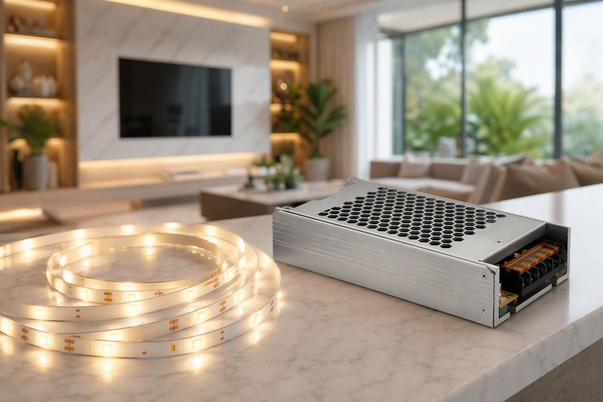
Choosing an LED power supply for a 24V system starts with one rule: confirm the LED product’s required driver type and voltage before comparing wattage, price, enclosure, or connectors.
For a typical 24V constant-voltage LED strip, the appropriate starting point is a regulated 24V DC constant-voltage power supply. From there, calculate the complete load, add a practical capacity margin, and verify the supply’s current rating, AC input, dimming method, installation format, environmental rating, connectors, and exact-model documentation.
Start With the LED Load, Not the Power Supply
“24V” alone does not establish compatibility. The LED strip, module, or fixture specification should identify:
- Whether it requires constant-voltage or constant-current power
- Its required output voltage or regulated current
- Its rated power consumption
- Whether and how it supports dimming
- Any limits on run length, wiring, controls, or installation conditions
Constant voltage versus constant current
Most conventional 24V LED strips contain groups of LEDs and onboard current-limiting components. They are designed to receive a regulated 24V DC input, with the strip drawing current according to its construction and installed length.
Bare high-power LEDs and some modules or fixtures instead require a driver that regulates a specified current while operating across a defined voltage range. These driver types are not interchangeable; the LED product specification controls the choice. LEDSupply explains the constant-voltage and constant-current distinction and why many strips use constant-voltage power.
A product marketed as a “24V LED” is therefore not automatically compatible with every supply labeled 24V. Confirm that the required output is specifically 24V DC, that the driver architecture is correct, and that the permitted voltage tolerance and control method match.
Power supply, driver, transformer, or adapter?
Sellers use several overlapping terms:
- Power supply usually describes a unit that converts an available input into a regulated electrical output.
- LED driver may refer to either a constant-voltage supply or a constant-current regulator.
- Transformer is often used loosely for an LED power supply, even when the product contains electronic regulation.
- Adapter commonly means a plug-in wall or desktop package with an attached output cable.
Do not choose by the name alone. Select by the electrical specifications printed on the exact model or stated in its datasheet.
Voltage must match
Do not connect a 24V supply to a 12V strip or assume that a 12V supply will operate a 24V strip correctly. Vendor guidance notes that a 12V driver may produce dim or no output from a 24V strip, while applying 24V to a 12V strip can cause failure. Follow the LED manufacturer’s specified voltage rather than treating voltage ratings as interchangeable. Inspired LED’s driver guide describes these voltage-mismatch consequences.
Use this decision sequence:
- Identify the required driver type.
- Confirm the exact DC output voltage.
- Calculate total watts and load current.
- Add an appropriate capacity margin.
- Match the AC input range and frequency to the available source.
- Choose the dimming architecture.
- Match the enclosure to the environment.
- Select the installation format.
- Verify connectors, terminals, and polarity.
- Read the documentation for the exact model and wattage variant.
Calculate the Required Watts and Amps
Start with the LED manufacturer’s rated maximum or design wattage—not a guess based on perceived brightness.
For a strip rated in watts per foot:
Total load watts = installed length in feet × watts per foot
For a strip rated in watts per meter:
Total load watts = installed length in meters × watts per meter
Keep the units consistent. Do not multiply meters by a W/ft rating or feet by a W/m rating.
If several strips, modules, or branches share one supply, calculate every branch and add the results:
Combined load watts = branch 1 watts + branch 2 watts + all other loads
Do not size the supply using only the longest branch.
Calculate load current at 24V
Once the total wattage is known:
Load current in amps = load watts ÷ 24V
This gives the expected LED load current before adding capacity headroom. The selected power supply must satisfy both its wattage and current ratings. The underlying relationship is power equals voltage multiplied by current, so a supply labeled 24V and 2.5A has a nominal capacity of 60W: 24V × 2.5A = 60W. TME’s sizing guide provides the load formula and explains deriving current from voltage and power.
Neither the 2.5A rating nor the 60W rating should be exceeded.
How much capacity headroom should you add?
Commercial sizing guides use several rules of thumb. Some recommend approximately 20% spare capacity, others suggest 20–30%, and another common method is to operate a supply at no more than 80% of its stated output. These are practical vendor recommendations, not a universal electrical-code requirement.
The 80% loading method is:
Minimum supply watts = calculated load watts ÷ 0.8
Be precise about what the percentages mean:
- Multiplying the load by 1.20 adds a margin equal to 20% of the calculated load.
- Dividing the load by 0.80 selects a supply 25% larger than the load and leaves 20% of the selected supply’s capacity unused.
Headroom does not replace manufacturer derating instructions. Ambient temperature, mounting orientation, cabinet ventilation, and other exact-model conditions may require a different selection.
Example 1: 10 feet at 4.4W/ft
A 24V strip is rated at 4.4W per foot, and the installation uses 10 feet:
- Load: 10 ft × 4.4W/ft = 44W
- Load current: 44W ÷ 24V = approximately 1.83A
- 80% method: 44W ÷ 0.8 = 55W
The result under that guideline is a minimum 55W supply rating. A standard 24V, 60W, 2.5A supply is a practical next size if its input, dimming method, enclosure, connectors, and operating conditions also match. Flexfire uses these same inputs and calculations in its worked example. See Flexfire’s 44W load and 60W supply example.
Example 2: 3 meters at 4.8W/m
For 3 meters of strip rated at 4.8W/m:
- Load: 3m × 4.8W/m = 14.4W
- Load current: 14.4W ÷ 24V = 0.6A
- With a 20% margin: 14.4W × 1.2 = 17.28W
The arithmetic target is therefore at least 17.28W. The selected supply must also have enough output-current capacity and satisfy every other project requirement. TME presents this 3m, 4.8W/m example and rounds the required supply rating to at least 18W under its selected margin. Review TME’s metric sizing example and 20–30% recommendation.
Example 3: two 30W branches
Two branches each consume 30W:
- Combined load: 30W + 30W = 60W
- Load current: 60W ÷ 24V = 2.5A
- With a 20% margin: 60W × 1.2 = 72W
The arithmetic target is at least 72W. The chosen model must provide the corresponding output-current capacity and accommodate the intended branch arrangement. A commercial installation guide uses the same 60W load and 72W result when applying a 20% margin. See the vendor’s 60W-to-72W sizing example.
Compact sizing worksheet
| Field | Project entry |
|---|---|
| Strip, module, or fixture model | |
| Required driver type | Constant voltage / constant current |
| Required output voltage | |
| Rated W/ft or W/m | |
| Installed length | |
| Branch 1 load | |
| Branch 2 load | |
| Other shared loads | |
| Combined load watts | |
| Load amps: watts ÷ 24V | |
| Chosen margin or loading rule | |
| Minimum supply wattage | |
| Minimum output-current capacity | |
| Proposed exact model and variant |
Understand Headroom, Oversizing, and Supply Limits
On a regulated constant-voltage supply, the wattage and amperage ratings describe available output capacity. A compatible load draws the current it requires, provided it remains within the supply’s operating limits.
A 24V constant-voltage supply with a higher amp or watt rating does not inherently push its full rated current through a smaller compatible LED load. A 24V load drawing 1A can generally be served by a compatible 24V supply rated above 1A, subject to the manufacturer’s minimum-load, protection, wiring, and installation requirements.
Spare capacity never makes the wrong voltage safe. A high-capacity 24V supply remains unsuitable for a 12V strip.
Why leave modest headroom?
Practical headroom avoids intentionally designing a continuously used system at the edge of its published output rating. It can also accommodate reasonable differences between calculated and actual load.
It should not be presented as a guarantee of lower temperature, longer life, or improved performance. Check the exact supply documentation for:
- Output derating at elevated ambient temperature
- Permitted mounting orientation
- Required ventilation and clearances
- Minimum-load requirements
- Continuous versus peak ratings
- Overload behavior
- Enclosure limitations
- Terminal and conductor limits
A fixed 20%, 25%, or 30% rule cannot override those instructions.
Minimum load is different from maximum capacity
Some dimmable drivers require a minimum connected load to operate as specified. That can create a compatibility problem when a large driver is paired with a very small strip.
For example, Armacost lists multiple wattage variants of its 24V dimmable driver and states that the 120W version requires at least a 24W load. The same page recommends a forward-phase CL-style or equivalent dimmer and warns that reverse-phase or ELV dimmers may reduce performance. Those details are specific to that product family and control arrangement, not universal rules for all 120W supplies. Review Armacost’s stated minimum-load and dimming conditions.
An extremely oversized supply may add cost and physical bulk while creating a minimum-load issue with some dimmable models. Select reasonable capacity rather than automatically buying the largest available unit.
Do not confuse DC output capacity with AC input consumption. Output watts, input watts, efficiency, standby consumption, power factor, and inrush current are separate specifications. Compare them only when the exact-model documentation provides the relevant values.
Plan Multiple Strips and Long Runs
One 24V power supply can operate several strips or modules when:
- Every connected load requires 24V DC constant-voltage power.
- Their combined load, including the chosen margin, remains within the supply’s ratings.
- Distribution wiring and connections accommodate the branch currents.
- The controls are compatible with the complete load.
- Each strip remains within its product-specific run limits.
Treat separate strips as parallel branches receiving 24V feeds rather than assuming one long daisy chain will maintain equal voltage throughout.
                 +---- positive and negative pair ---- Strip A
24V supply ------+---- positive and negative pair ---- Strip B
                 +---- positive and negative pair ---- Strip C
            distribution point
This sketch shows the electrical concept, not a complete installation design. Distribution hardware, terminal capacity, branch protection, cable selection, and control zoning must be determined for the actual project.
Maximum run length is strip-specific
A strip’s maximum recommended run depends on its circuit design, wattage, copper construction, and allowable voltage drop. It cannot be inferred solely from “24V.”
For example, Flexfire states a maximum 42-foot run for its named 24V Architectural Series and suggests parallel runs for longer installations. That 42-foot figure belongs only to that product series and should not be applied to other strips. Flexfire identifies the product-specific 42-foot limit in its strip-selection guide.
Recognize voltage-drop symptoms
The far end of a long strip may appear dimmer than the end nearest the feed. On some white or color-changing products, color can also become less consistent along the run.
Relevant variables include:
- Branch current
- One-way cable distance
- Conductor size and material
- Strip construction
- Connection resistance and quality
- Number and placement of feeds
- Acceptable voltage loss
Possible design responses include shortening branches, moving the supply closer, using an appropriately larger conductor, installing separate parallel feeds, injecting power at additional points, or feeding both ends when the strip manufacturer permits it.
A larger-wattage supply alone does not correct voltage loss caused by long or undersized downstream wiring. If the existing supply maintains its specified output under load, additional supply capacity does not remove resistance from the cable, connectors, or strip conductors.
Preserve polarity at every feed. Confirm the supply’s V+ and V− markings, strip pads, and connector documentation rather than relying only on wire colors.
High-power and multi-output supplies are available, but neither one large output nor several smaller outputs is universally preferable. Branch loading, output limitations, control zoning, physical distribution, and exact-model documentation should determine the architecture.
Choose the Installation Format
Select the package by use case, accessibility, connection method, and environment—not by assuming one format is always superior.
Plug-in wall or desktop adapters
A plug-in adapter can be convenient for a small indoor installation because it avoids permanent mains connections at the lighting equipment. It is suitable only when all of these specifications match:
- 24V DC regulated output
- Constant-voltage operation
- Sufficient watts and amps
- Correct output-connector dimensions
- Correct connector polarity
- Compatible input plug, voltage range, and frequency
- Appropriate location rating
- Compatible dimming arrangement
A connector described merely as “barrel” is not enough. Verify the inner and outer dimensions, polarity, and current rating.
Hardwired drivers
A hardwired driver may fit a permanent or wall-controlled installation, but the exact manufacturer documentation must address its input connections, enclosure or junction-box arrangement, cable restraint, terminations, mounting, accessibility, and any applicable installation requirements.
A built-in junction box can simplify part of the physical installation, but it does not replace the model’s instructions.
Metal- and plastic-enclosed supplies
Metal- and plastic-enclosed supplies are package formats, not complete suitability ratings. Some metal-enclosed units have accessible terminal blocks or ventilation openings; plastic-enclosed products vary in connection method, mounting arrangement, and environmental protection.
Do not infer electrical class, weather resistance, ventilation requirements, or suitability for an occupied area from enclosure material alone.
Weather-resistant and waterproof-marketed supplies
These formats may be candidates for humid or exposed environments only after the exact enclosure or location rating and the complete installation method have been verified. The word “waterproof” in a catalog title does not establish a specific IP rating or approval for every outdoor use.
Market options by format
Retailer catalogs illustrate the range of available 24V formats. Ecolocity, for example, advertises plug-in, dimmable, waterproof-marketed, multi-output, enclosed, and high-power products, with listed capacities extending from 24W to 1500W. These are seller-listed catalog examples, not recommendations that the highest-capacity units belong in typical residential projects. See Ecolocity’s advertised 24VDC formats and capacities.
| Format | Typical fit | What to compare | Main cautions |
|---|---|---|---|
| Wall adapter | Small indoor strip | Output voltage, capacity, plug type, barrel dimensions, polarity | Verify location rating and connector current capacity |
| Desktop adapter | Under-cabinet or furniture lighting | AC cord, DC lead, output connector, dimensions | Keep installation conditions consistent with exact-model instructions |
| Hardwired dimmable driver | Permanent or wall-controlled lighting | Input range, dimming protocol, minimum load, enclosure arrangement | Match the dimmer type and follow model-specific installation documentation |
| Metal-enclosed supply | Equipment space or protected enclosure | Terminal layout, ventilation, mounting, output capacity | Do not assume exposed-terminal or open-vent designs suit every location |
| Plastic-enclosed supply | Compact protected installation | Connection method, mounting, environmental rating | Plastic construction alone does not establish insulation class or weather resistance |
| Waterproof-marketed supply | Potentially damp or exposed location | Exact IP/location rating, cable entries, lead arrangement | Evaluate the assembled installation, not only the supply body |
| Multi-output unit | Several branches or control zones | Output allocation, per-output limits, total capacity | Confirm whether outputs are independently limited |
| High-power unit | Large multi-branch project | Distribution plan, dimensions, output current, documentation | Higher capacity can increase distribution and installation complexity |
Catalog prices, availability, warranty terms, ratings, and variant details can change. Compare exact model numbers and current datasheets rather than ranking product families by a displayed starting price.
Use-case shortlist
- Small under-cabinet run: Consider a correctly sized plug-in adapter with verified connector dimensions and polarity.
- Hidden indoor architectural run: Compare enclosed or hardwired supplies that fit the available service space and specified mounting conditions.
- Wall-dimmer installation: Use a purpose-built dimmable driver matched to the control method.
- Damp or outdoor location: Verify the supply, cable entries, connectors, splices, and boxes for the actual exposure.
- Multiple high-load branches: Compare suitable distribution or multi-output arrangements using project-specific branch loads.
For each shortlisted model, record its exact part number, output voltage and current, wattage, input range and frequency, dimming protocol, minimum load, enclosure rating, connector or terminal type, dimensions, mounting conditions, and source document. A family name or retailer category is not enough.
Match the Supply to the Dimming System
“Dimmable” is not a universal compatibility label. The LED load, supply, controller, dimmer, and protocol must work together.
Three different dimming categories
AC-input phase-cut dimming controls a purpose-built driver from a mains-side wall dimmer. Compatibility may depend on whether the driver and dimmer use forward-phase, reverse-phase, TRIAC, ELV, or MLV methods. Do not assume that these labels are interchangeable.
Low-voltage PWM dimming places a compatible controller on the 24V DC side:
AC source → compatible 24V constant-voltage supply → PWM controller → LED strip
The controller must be rated for the supply voltage, total current, required channel count, and selected LED type.
Control-input dimming, including 0–10V and DALI, uses a driver designed for the selected protocol. These systems may require separate control conductors and can have model-specific minimum-level or full-off behavior. Inspired LED distinguishes PWM, 0–10V, and TRIAC or phase-cut systems and recommends checking the exact driver and control combination. See its comparison of LED dimming architectures.
Do not assume an ordinary supply accepts wall dimming
A non-dimmable supply should not be connected to an AC wall dimmer unless the exact supply documentation approves that arrangement. For DC-side dimming, the alternative is generally a compatible low-voltage controller installed after a suitable constant-voltage supply.
Before buying a dimmable driver, verify:
- Dimming protocol
- Forward- or reverse-phase requirements
- TRIAC, ELV, or MLV compatibility
- Tested dimmer list
- Minimum connected load
- Maximum controlled load
- Advertised low-end level
- Whether the system switches fully off
- Manufacturer information about flicker or buzz
- Required control conductors
- Compatibility with the selected strip or fixture
Armacost, for example, says its 24V dimmable driver family supports AC-side and low-voltage DC controls, recommends a forward-phase CL-style or equivalent dimmer, and cautions that reverse-phase or ELV controls may reduce performance. Its smooth or flicker-free statements remain manufacturer claims rather than independent test results. Review Armacost’s control recommendations.
Dimming decision tree
-
No dimming required - Choose a compatible non-dimmable 24V constant-voltage supply.
-
Low-voltage controller required - Use a compatible 24V supply followed by a properly rated PWM or multichannel controller.
-
0–10V or DALI building control - Choose a driver explicitly designed for the protocol and verify its control wiring and off behavior.
-
Wall-switch phase-cut dimming - Choose a purpose-built phase-cut driver, then match its phase type, tested controls, load range, and documented wiring arrangement.
Match the Enclosure and Ratings to the Location
Dry-location, damp-location, wet-location, water-resistant, waterproof, and IP-rated descriptions should not be treated as equivalent.
An IP number provides ingress-protection information under defined conditions. It does not, by itself, settle every question about mounting, cable entries, corrosion, sunlight exposure, local requirements, or suitability near pools, fountains, or standing water.
Catalog terminology varies. For example, Solid Apollo seller-lists one 24V, 1A, 24W wall supply with a 100–240V AC input, a 5.5mm barrel connector, and an IP55 enclosure rating. Those are claims for that particular item, and the supplied page does not state the connector polarity or complete inner and outer dimensions. Review the retailer’s exact 24W adapter specifications.
An IP55 or IP65 label does not automatically establish suitability for every outdoor exposure, pool area, fountain, standing-water condition, or submerged installation. Verify the exact model’s approved use and installation instructions.
The completed installation may also depend on:
- Cable glands and entries
- Input and output connectors
- Splices and end seals
- Junction boxes
- Mounting orientation
- Drainage and exposure
- Protection from mechanical damage
- Whether specified seals or cables have been modified
The strip and power supply require separate evaluation. A sealed LED strip does not transfer its rating to an indoor power supply, open connector, or unsealed splice. LED Lighting Zone’s guide to LED-strip IP ratings and location selection provides strip-side context, but the power source and every connection still require their own appropriate ratings.
Follow the exact supply’s stated clearances, mounting position, ventilation, and ambient-temperature limits, particularly inside cabinets and other enclosed spaces. Where the design permits, placing the supply in a protected location reduces direct exposure without changing the need for properly rated downstream components.
This guide addresses component selection for low-voltage LED systems rather than mains-wiring procedures. Hardwired and panel work may require a qualified electrician and must follow manufacturer instructions and applicable local requirements; the publication’s electrical-work boundary is stated in its terms.
Use an Exact-Model Buying and Troubleshooting Checklist
Family pages frequently place several wattage variants on one page. A detailed specification table may describe only the currently selected model rather than every version in the family. Verify the exact part number before buying or replacing a supply.
Pre-purchase checklist
Check these items in order:
- LED driver type: constant voltage or constant current
- Output: exactly 24V DC where required
- Calculated load: total watts for every connected branch
- Output current: load watts divided by 24V
- Headroom: selected practical margin or manufacturer rule
- AC input range: voltage and frequency compatible with the available source
- Dimming protocol: none, PWM, phase-cut, 0–10V, DALI, or another specified method
- Minimum load: especially for dimmable drivers
- Format: plug-in, hardwired, enclosed, junction-box, sealed, or multi-output
- Environment rating: appropriate for the actual exposure
- Connector or terminals: correct type, dimensions, and capacity
- Polarity: confirmed from markings and documentation
- Physical dimensions: including space for cables and access
- Ventilation: clearance, orientation, and ambient limits
- Warranty: exact-model terms and exclusions
- Protection features: only those explicitly documented for the selected model
Overload, short-circuit, overvoltage, overtemperature, and automatic-shutoff functions are exact-model claims. Do not assume that every LED supply includes all of them or that different models respond to faults in the same way.
Likewise, UL Listed, UL Recognized, ETL, Class 2, FCC, CE, and IP are different advertised markings or classifications. Do not infer one from another. Confirm the exact model’s claims in its documentation and, where necessary, through the relevant certification record or local authority. A retailer catalog showing 24V products with different combinations of these labels illustrates why variant-level checking matters. Compare the seller-listed attributes across constant-voltage supply formats.
Exact-model comparison card
Complete one card for every shortlisted model:
| Specification | Model A | Model B | Model C |
|---|---|---|---|
| Manufacturer and exact part number | |||
| Driver type | |||
| Output voltage | |||
| Rated output current | |||
| Rated output watts | |||
| AC input voltage and frequency | |||
| Dimming protocol | |||
| Tested controls | |||
| Minimum load | |||
| Enclosure or location rating | |||
| Connector or terminal details | |||
| Dimensions | |||
| Mounting and ventilation limits | |||
| Advertised approvals | |||
| Warranty | |||
| Datasheet or manual checked |
This approach makes gaps visible. A model should not receive a favorable assumption simply because a retailer page leaves a field blank.
Troubleshooting by symptom
Do not open, modify, or probe mains-connected equipment based on this article. Use the manufacturer’s troubleshooting procedure and qualified assistance where the work falls outside low-voltage checks.
| Symptom | Checks |
|---|---|
| No light | Confirm that the selected supply is specified for 24V DC output; check low-voltage polarity, connectors, controller settings, remote pairing, and documented protection-mode behavior. |
| Dim light everywhere | Compare the complete load with the supply’s watt and amp ratings; verify the required output voltage, controller limits, connections, and exact supply variant. |
| Far end is dimmer | Inspect cable distance and conductor size, branch layout, connector resistance, strip run length, and the need for parallel feeds or permitted power injection. Do not assume more supply wattage will correct downstream voltage loss. |
| Cycling or intermittent shutdown | Compare the combined load with the rated output; inspect low-voltage connections and check the model’s ventilation, mounting, ambient, and protection requirements. |
| Flicker, buzz, or poor low-end dimming | Verify the dimming protocol, phase type, minimum load, tested dimmer list, control wiring, and controller capacity. Check documented full-off behavior. |
| Supply works until another branch is added | Recalculate the combined watts and current, including all channels or modules; check controller and distribution-terminal ratings. |
| Replacement supply does not work | Recheck 24V versus 12V, DC versus AC output, constant voltage versus constant current, connector dimensions and polarity, minimum load, and exact-variant ratings. |
| Connector or cable becomes unusually warm | Stop using the system and have the connector, conductor, terminals, load, and manufacturer requirements checked before further operation. Replace damaged or unsuitable components rather than relying on a larger supply. |
Frequently Asked Questions
What size power supply do I need for a 24V LED strip?
Multiply the installed strip length by its rated watts per foot or watts per meter. Add every branch sharing the supply, then divide the combined watts by 24V to calculate load current.
Apply a clearly identified practical margin unless the manufacturer specifies another sizing method. The final supply must meet both the wattage and output-current requirements.
Under the 80% loading method:
Minimum supply watts = total load watts ÷ 0.8
That method selects a supply 25% larger than the calculated load and leaves 20% of the supply’s rating unused.
Can I use a 24V power supply with a higher amp or watt rating than the LED load?
Generally, yes—provided the load requires regulated 24V DC constant-voltage power and every other specification matches. The amp and watt ratings describe available capacity; a compatible load draws the current it requires.
Do not use extra capacity as a substitute for correct voltage. Also check minimum-load requirements, dimming compatibility, physical size, ventilation, and manufacturer derating. Excessive oversizing can be counterproductive when a dimmable driver requires a minimum connected load.
Can multiple 24V LED strips share one power supply?
Yes, when all strips require 24V DC constant-voltage power and their combined buffered load remains within the supply and controller ratings.
Use separate parallel feeds where appropriate rather than assuming one long daisy chain will maintain even voltage. Account for cable distance, branch current, conductor size, terminal capacity, polarity, and each strip’s product-specific run limit.
Can I dim a 24V LED strip with any dimmable power supply?
No. “Dimmable” does not identify one universal control method.
A system may use an AC phase-cut driver, a compatible constant-voltage supply followed by a PWM controller, or a driver designed for 0–10V, DALI, or another protocol. Verify the driver, strip, controller, dimmer phase type, minimum load, control conductors, and tested compatibility as one system.
Do not place a non-dimmable supply on an AC wall dimmer unless the exact supply documentation approves that arrangement.
Is an IP55 or IP65 24V power supply suitable for outdoor use?
Not automatically. Suitability depends on the exact exposure, approved use, mounting instructions, cable entries, connectors, boxes, splices, temperature limits, and completed installation.
Do not assume that either rating approves a supply for every type of rain exposure, standing water, pool area, fountain, or submersion. Verify the exact model and preserve the intended protection throughout the assembled system.
One-Page Selection Summary
Use this sequence while comparing datasheets:
- Confirm that the LED product requires 24V DC constant-voltage power.
- Add the rated wattage of every strip, module, and branch.
- Divide total watts by 24V to calculate load current.
- Add a clearly identified practical capacity margin.
- Select a supply that meets both the wattage and amp requirements.
- Confirm that the AC input-voltage and frequency range covers the available source.
- Choose the dimming architecture before buying the driver.
- Check minimum-load and tested-control requirements.
- Match the package to plug-in, hardwired, enclosed, sealed, or multi-output use.
- Verify the environmental rating for the exact location.
- Confirm connector dimensions, terminal capacity, and polarity.
- Check dimensions, mounting, clearances, ventilation, and ambient limits.
- Verify advertised approvals, protection features, warranty, and exact model number.
- Plan parallel branches and voltage-drop control separately from supply capacity.
Voltage compatibility comes first. Extra wattage does not cure downstream voltage drop, and labels such as “dimmable” or “waterproof” do not establish universal compatibility. Hardwired and water-adjacent installations require exact manufacturer documentation and, where appropriate, qualified electrical review.