
12V LED Power Supply: Match Voltage, but Size for the Load
Total all loads, divide total watts by 12 and apply a planning margin to determine required watts and amps. Then check dimming, wiring and environment.
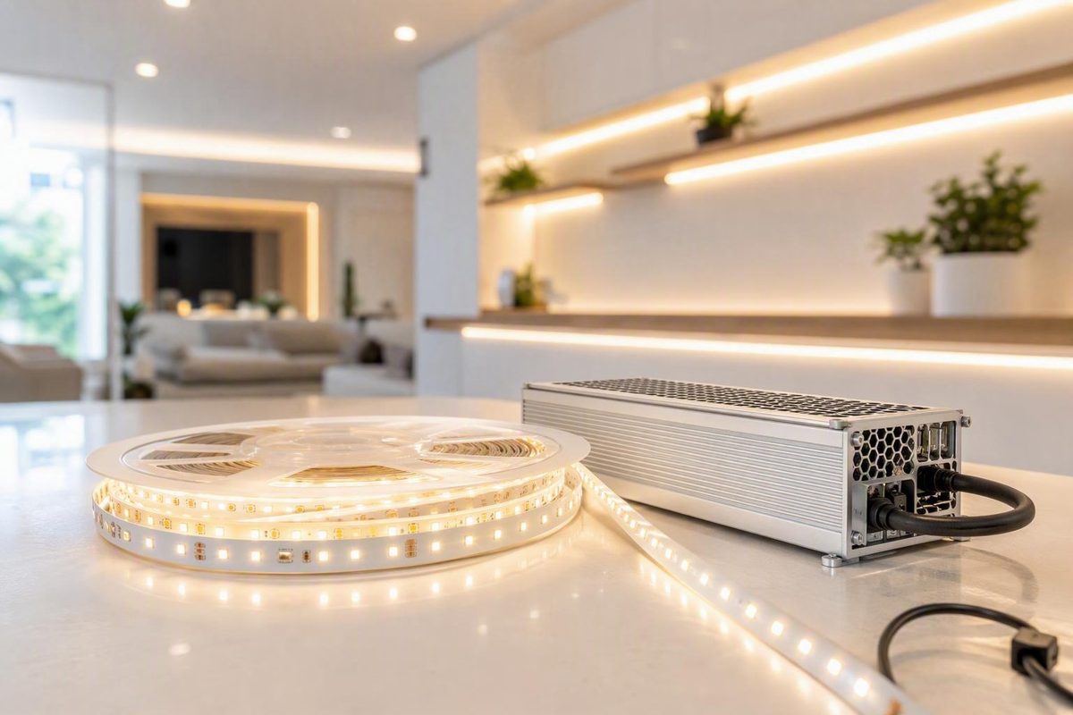
Choosing a 12V LED power supply involves more than finding an adapter with “12V” on its label. The LED load must be designed for 12V constant-voltage power, and the supply must provide enough output current and wattage for the complete installation. It must also suit the dimmer or controller, wiring layout, enclosure, ambient conditions, and installation method.
Start with the LED product rather than the power-supply listing. Once you know the load’s required voltage, driver type, and documented power consumption, you can calculate capacity, add reasonable planning headroom, and compare suitable supply formats. The same process applies to LED strips, address lighting, under-cabinet lighting, signs, modules, and similar low-voltage systems.
Start by confirming what the LED load actually requires
A 12V constant-voltage power supply converts its input power into regulated 12V DC for a compatible load. It maintains that output voltage while making current available up to its rated limit.
Two conditions must therefore be satisfied:
- The LED product must specify 12V DC input.
- It must be designed to operate from a constant-voltage source.
A finished 12V strip or module intended for constant-voltage input should be connected to regulated 12V DC. A 24V supply is not interchangeable with it. Check the product label, package, installation instructions, or specification sheet for the required input voltage and supply type.
This built-in current control allows the complete strip to operate from a matching constant-voltage source. DigiKey’s explanation of constant-voltage and constant-current LED drivers similarly distinguishes resistor-equipped fixed-voltage products from LEDs that need externally regulated current.
Do not assume every product containing LEDs belongs in that category. Bare LEDs, many high-power LEDs, and some chip-on-board arrays generally require a constant-current driver. That driver is selected by its regulated current and by an output-voltage range that accommodates the LED or LED string. A generic 12V supply does not provide suitable current regulation merely because “12V” appears somewhere in the product description.
Appearance is not a reliable guide. A flexible strip, rigid module, puck light, COB assembly, or finished fixture may contain its own current-limiting electronics—or may rely on an external driver. Verify:
- Required input voltage
- AC or DC input
- Constant-voltage or constant-current operation
- Rated power or current
- Dimming and control requirements
- Polarity and connector arrangement
- Maximum run length or grouping restrictions
- Any required companion driver or controller
Retail terms are also inconsistent. “Driver,” “transformer,” “adapter,” and “power supply” may refer to different electrical designs. A product called an LED driver might provide constant voltage or constant current, while a product called a transformer may actually be an electronic switching supply.
Treat the name as a shopping category, not proof of compatibility. The load documentation and the supply’s complete output specification are what matter.
Calculate the required watts and 12V output current
Once you have confirmed that the load accepts 12V constant-voltage power, calculate its total demand.
For a strip specified in watts per foot:
Total LED watts = watts per foot × installed feet
For a strip specified in watts per meter:
Total LED watts = watts per meter × installed meters
Use the power density for the exact strip being installed. Two products with the same voltage and physical dimensions can have different LED densities, circuit designs, brightness levels, and power demands.
For several strips, fixtures, or modules on one supply, calculate each load and add them together:
Combined load = load 1 + load 2 + load 3 + all remaining loads
Add the loads before applying any planning margin. Use the length that will actually be energized, not the amount purchased. If 10 feet from a 16-foot reel will be installed, calculate the demand for 10 feet.
Next, convert the total load to nominal 12V output current:
Nominal output amps = total watts ÷ 12 volts
This is the expected DC-side current at the stated load. It is not the supply’s AC input current, which also depends on input voltage and the supply’s conversion characteristics.
Worked example: one 10-foot strip
Suppose a 12V strip is rated at 5.5 watts per foot and the project uses 10 feet:
5.5W/ft × 10 ft = 55W55W ÷ 12V = 4.58A
The nominal load is therefore 55 watts and approximately 4.6 amps.
If a 20% planning reserve is applied:
55W × 1.20 = 66W66W ÷ 12V = 5.5A
The selected supply should provide regulated 12V DC and at least 66W or 5.5A of planned capacity. The underlying LED load remains approximately 4.6A; 5.5A is the corresponding supply capacity after the 20% margin. These figures follow the example in Waveform Lighting’s LED-strip power-supply calculator.
Keep the three relevant figures separate:
- Nominal LED load: 55W
- Nominal LED current: approximately 4.6A
- Supply capacity after a 20% reserve: at least 66W or 5.5A at 12V
If no 66W model is available, choose the next suitable standard size above it. Do not round down.
Worked example: four separate runs
Suppose four compatible 12V runs each consume 12 watts:
4 × 12W = 48W48W ÷ 12V = 4A48W × 1.20 = 57.6W57.6W ÷ 12V = 4.8A
A compatible 12V, 60W supply is a straightforward nominal choice because it provides up to 5A. The four-run calculation and 20% reserve are based on LEDSupply’s power-supply selection example.
The watt and amp ratings should agree. At 12V:
60W ÷ 12V = 5A
If a listing claims 60W but gives an output-current rating substantially below 5A at 12V, inspect the full datasheet. The product title may be incomplete, may describe combined outputs, or may refer to a rating under different conditions.
Quick 12V watts-to-amps table
| 12V load | Nominal output current |
|---|---|
| 12W | 1A |
| 24W | 2A |
| 36W | 3A |
| 48W | 4A |
| 60W | 5A |
| 72W | 6A |
| 96W | 8A |
| 120W | 10A |
This table is only a conversion aid. It does not include planning headroom, thermal derating, controller consumption, voltage drop, or product-specific restrictions.
Choose sensible capacity headroom without treating it as a universal law
Selecting a supply whose rating exactly equals the nominal load leaves no planning allowance for operating conditions, specification tolerances, or modest changes in the connected system.
Commercial sizing guides commonly recommend approximately 20% to 30% spare capacity. Another formulation is to keep the nominal load at or below about 80% of the supply rating. For example:
48W ÷ 0.8 = 60W
These are practical selection rules, not universal electrical-code requirements. TME recommends a 20% to 30% power margin, while Flexfire presents an 80% loading method. Both are vendor guidance; the selected supply’s documentation takes precedence.
Usable output can depend on conditions such as:
- Ambient and enclosure temperature
- Ventilation
- Mounting orientation
- Input-voltage range
- Continuous or intermittent operation
- Cooling method
- Thermal derating
- Connected-load characteristics
If the datasheet requires derating in a hot or restrictive enclosure, a generic 20% margin may not be enough. Apply the manufacturer’s documented derating first, then verify that the resulting usable capacity still exceeds the planned load.
A higher current rating is generally acceptable when the voltage and load type match. A 12V 5A supply makes up to 5A available; it does not automatically force 5A through a compatible load that normally draws 3A.
That principle does not make voltage interchangeable. Additional current capacity can be acceptable, but 24V applied directly to an ordinary 12V strip is excessive voltage—not useful headroom.
Substantial oversizing is not automatically beneficial. Before selecting a much larger unit, check the model’s documentation for:
- Minimum-load requirements
- Low-load operation
- Dimming behavior
- Standby consumption
- Physical size
- Cooling or fan behavior
- Terminal arrangement
- Manufacturer restrictions
Some products may have model-specific minimum-load or dimming limitations. Do not assume that all oversized supplies behave poorly, but do verify the selected model’s documented performance with the actual controller and load.
A practical sequence is:
- Calculate the nominal load from documented product values.
- Apply a clearly identified planning margin.
- Round up to an available standard size.
- Confirm both the watt and amp ratings.
- Apply any documented thermal or environmental derating.
- Verify the final choice against the complete datasheet.
Match the supply format to the installation
Electrical capacity is only one selection criterion. A 60W plug-in adapter, 60W hardwired driver, and 60W caged supply may all produce 12V DC but suit different installations.
Plug-in adapters
Plug-in adapters are often convenient for accessible indoor projects, prototypes, furniture lighting, and lower-power installations near a receptacle. They can simplify replacement and avoid a permanent connection at the supply.
Check:
- DC connector dimensions
- Connector polarity
- Cord and connector current ratings
- Input-voltage range
- Ventilation instructions
- Permitted mounting location
- Accessibility requirements stated by the manufacturer
Barrel plugs that look alike may have different inside dimensions or polarity. Confirm every mating connector rather than relying on appearance.
Whether an adapter may be concealed, placed in cabinetry, or operated in a confined space is product-specific. Follow its installation instructions instead of treating “plug-in” as permission for any location.
Hardwired drivers
Hardwired supplies are commonly considered for permanent architectural lighting. Depending on the model, they may have lead wires, terminal compartments, junction-box arrangements, or fixed mounting provisions.
Check the instructions for the exact product to determine:
- How input and output conductors are connected
- Whether grounding is required
- What strain relief is required
- Whether a junction box or separate enclosure is needed
- Permitted mounting orientation
- Required clearances and ventilation
- Whether the unit must remain accessible
Do not infer that a hardwired product may be buried behind finished surfaces, covered with insulation, or installed in an arbitrary enclosure. Those decisions must come from the product documentation and locally applicable installation requirements.
Enclosed or caged supplies
Metal-cased, ventilated, open-frame, and caged supplies are separate formats rather than simply larger adapters. Some have screw terminals or openings that affect how they may be mounted and guarded.
Before buying, verify:
- Whether terminals are exposed
- Whether a terminal cover is supplied
- Whether an additional enclosure is specified
- Grounding or insulation requirements
- Ventilation openings and required airflow
- Mounting-hole locations and orientation
- Permitted access and service arrangements
- Environmental limitations
Do not place a ventilated or exposed-terminal unit where moisture, debris, or accidental contact can reach it unless the manufacturer’s instructions permit that installation and the required protection is provided.
Compact and junction-box-compatible models
Compact supplies can be useful for address lighting, signs, shallow cabinets, and other installations where space is limited. Measure the complete installation volume, including room for conductor bends, connectors, strain relief, mounting hardware, and any required airflow.
Luxello provides a model-level example. Its DR-1 is listed as a 12V DC, 1A, IP44 unit measuring 3 by 1 by 0.75 inches and is described as fitting a standard 4-inch junction box. Its DR-2 is listed as 12V DC, 1.67A, 20W, and IP67. The page’s introductory description broadly calls the product an IP67 outdoor driver, but the individual options identify the DR-1 as IP44 and the DR-2 as IP67. That inconsistency illustrates why the exact option and cut sheet must be checked rather than relying on category copy; see the Luxello model specifications.
These models are examples of differing form factors and ratings, not universal recommendations.
Multi-output and distributed systems
Verify:
- Total combined capacity
- Any per-output or per-channel limit
- Whether outputs are electrically common or isolated
- Maximum branch current
- Distribution-block and connector ratings
- Controller limits
- Conductor requirements
- Any manufacturer-specified branch protection
Every branch still needs to be designed for its actual current and route. A supply with ample total capacity can still be limited by a controller channel, connector, terminal, or conductor.
Retail catalogs commonly separate non-dimmable, dimmable, plug-in, caged, multi-output, and weather-resistant products. That distinction reinforces the central buying rule: voltage and wattage are necessary filters, but they are not sufficient.
Plan the dimming and control architecture before buying
Not every 12V LED power supply is dimmable. If a product is labeled non-dimmable, treat it as such unless its manufacturer documents an approved control arrangement.
Control generally occurs either on the low-voltage side after the supply or through the input or control interface of a compatible dimmable driver.
Low-voltage PWM control
In a common constant-voltage strip system, the power supply provides steady 12V DC and a compatible pulse-width-modulation controller is installed between the supply and LED load.
A basic white-light arrangement is:
AC source → 12V power supply → PWM dimmer → LED strip
An RGB or tunable-white arrangement is:
AC source → 12V power supply → multichannel controller → LED strip
The controller must accept 12V input and support the load type. Confirm both its total current rating and any per-channel limits.
Do not infer universal PWM compatibility from the words “12V power supply.” Verify that the supply, controller, and LED product approve the proposed wiring arrangement.
Input-side phase or TRIAC dimming
TRIAC and phase-dimming arrangements control power on the AC side. They require a driver specifically designed for the selected dimming method, wall dimmer, and connected LED load.
A typical arrangement is:
Compatible wall dimmer → compatible phase-dimmable 12V driver → LED load
A conventional non-dimmable adapter should not be assumed to become properly dimmable merely because it is connected to a household wall dimmer.
Compatibility can depend on:
- Leading-edge or trailing-edge operation
- Minimum and maximum connected load
- Dimming range
- Wiring arrangement
- Exact driver model
- Exact dimmer model
- LED load characteristics
0–10V, DALI, and DMX
These are distinct control methods, not interchangeable labels:
- 0–10V uses a compatible low-voltage control interface.
- DALI is a digital lighting-control protocol.
- DMX is a digital control system commonly used for multichannel and color applications.
Each requires compatible equipment throughout the control path. A 0–10V input does not make a driver DALI-compatible, and adding a DMX decoder does not make every power supply dimmable. Supplier guidance identifies PWM, 0–10V, DALI, and DMX as separate approaches whose availability depends on the selected device (OMCH’s driver and power-supply overview).
Treat dimming as a system-level check covering:
- Power supply or driver
- Wall dimmer or control interface
- Low-voltage controller
- LED strip, module, or fixture
- Minimum and maximum load
- Total and per-channel current
- Wiring topology
- Desired dimming range
- Smart-home gateway, if used
Use this decision aid:
- Simple on/off lighting: choose a non-dimmable supply if no brightness control is required.
- PWM strips and color systems: place a compatible low-voltage controller between the 12V supply and load.
- Wall-dimmer or building-control systems: choose a 12V driver explicitly rated for the intended input-side or control-side method.
Account for voltage drop, distribution, and multiple LED runs
Total supply capacity and voltage delivered to the far end of a strip are different design questions.
For the same wattage, a 12V system carries more current than a 24V system:
60W ÷ 12V = 5A60W ÷ 24V = 2.5A
As current passes through conductors, connectors, terminals, and strip copper, resistance produces voltage loss. The power supply may still measure 12V at its terminals while the load receives less voltage farther along the circuit.
Possible signs of excessive voltage drop or connection resistance include:
- Reduced brightness toward the far end
- A visible brightness gradient
- Color shift under heavier loads
- Unstable operation when brightness or channel demand rises
Those symptoms are not exclusive to voltage drop. Strip defects, poor connections, controller limits, and product-specific run-length restrictions can produce similar behavior. Measure voltage at relevant points while the system is operating and inspect the complete path.
Depending on the product instructions and installation, possible remedies include:
- Shortening the feed
- Using larger conductors
- Dividing the installation into shorter parallel branches
- Feeding the strip from its center
- Feeding both ends where permitted
- Adding approved power-injection points
- Moving the supply or distribution point closer to the load
Power injection brings additional 12V and return conductors to another approved point along the load. Polarity and conductor routing must remain correct, and shared-supply or multiple-supply arrangements must follow the strip and controller instructions.
Buying a higher-wattage 12V supply does not by itself recover voltage lost in long or undersized wiring. If both the original and replacement supply regulate their terminals at 12V, the distribution path still has to be corrected.
Running several strips from one supply
Several compatible strips may share one supply when:
- Every load accepts 12V constant-voltage input.
- Every load is included in the capacity calculation.
- The selected supply provides adequate planned output.
- The topology is permitted by the product documentation.
- Controllers, conductors, connectors, terminals, and branches are adequately rated.
- Voltage delivery is evaluated along each path.
Whether that topology is appropriate depends on the selected strip and controller.
The supply’s overall rating does not increase the rating of downstream components. A connector or controller channel can remain the limiting part of the system even when the supply has spare capacity.
Branch protection and conductor selection
When one high-capacity supply serves several smaller branches, the documentation or applicable installation requirements may call for branch protection. Fuses are generally intended to protect conductors, but they cannot guarantee that every damaged strip will remain cool; the WLED calculator specifically cautions that a defective strip may overheat locally despite a cable-protection fuse.
Do not choose conductor size, fuse rating, or maximum cable length from a universal online table. Determine them from the actual current, conductor length, ambient temperature, insulation, routing, bundling, terminal ratings, allowed voltage drop, product instructions, and locally applicable requirements.
Use the manufacturer’s documented maximum or another clearly bounded design condition rather than relying only on a low-brightness test pattern.
Check environment, thermal conditions, and the complete datasheet
Before purchasing, read the full product documentation rather than relying on a marketplace title or search filter.
At minimum, verify:
- Regulated 12V DC output
- Constant-voltage operation
- Rated output watts and amps
- Compatible AC input-voltage and frequency range
- Dimming or control method
- Minimum and maximum load, if specified
- Physical dimensions
- Lead, plug, connector, or terminal type
- Operating-temperature range
- Ventilation instructions
- Mounting orientation and clearances
- Indoor, damp, wet, or other location limitations
Also check whether the manufacturer documents:
- Over-current protection
- Short-circuit protection
- Over-voltage protection
- Over-temperature protection
Do not assume these protections are present simply because the unit is marketed for LEDs. If they are listed, determine how they operate: automatic recovery, reduced output, latched shutdown, or a required power cycle.
For permanent, demanding, or control-sensitive installations, additional specifications may matter:
- Efficiency at the relevant load
- Thermal derating curves
- Ripple and output noise
- No-load and minimum-load behavior
- Standby consumption
- Grounding or insulation class
- Power-factor information
- Electromagnetic-compatibility information
- Audible noise
- Warranty and expected service conditions
- Applicable safety or regulatory markings
Applicable requirements depend on the country, installation method, building type, location, equipment class, and local enforcement. Confirm the requirements for the place where the equipment will actually be installed.
Understand what an IP rating does—and does not—cover
An ingress-protection rating is a model-specific enclosure claim. It does not automatically make the complete lighting installation suitable for outdoor, wet, or water-adjacent use.
The complete system also includes:
- Cable entries and lead exits
- Cut strip ends
- Splices
- Connectors
- Controllers
- Junction boxes
- Mounting penetrations
- Mains connections
- Drainage and condensation paths
Each component and connection must suit the environment. Verify the exact model rather than relying on a general “waterproof” category description.
Thermal conditions still matter. Placing a ventilated indoor supply inside an improvised sealed box may change its operating environment. If the supply requires airflow or thermal derating, use only an enclosure and installation arrangement supported by its instructions.
Low-voltage load calculations do not provide the information needed for mains-side hardwiring. Follow the product instructions and locally applicable requirements, and use appropriately qualified help where required.
Use a final selection and troubleshooting checklist
Before purchasing:
- Confirm the load type. Verify that the LED product accepts constant-voltage input.
- Confirm the voltage. Select regulated 12V DC for a compatible 12V load.
- Total every load. Use documented watts per foot, meter, fixture, or module.
- Calculate nominal current. Divide total watts by 12.
- Add stated headroom. Convert the planned wattage back to amps and apply any documented derating.
- Choose the format. Select a plug-in, hardwired, enclosed, compact, multi-output, or environmentally rated model as appropriate.
- Confirm control compatibility. Check the supply, dimmer, controller, and load as one system.
- Evaluate distribution. Account for feed length, branches, terminals, connectors, and permitted injection points.
- Audit the datasheet. Verify input range, temperature limits, protections, mounting instructions, and applicable markings.
- Plan inspection and replacement. Follow the manufacturer’s access and service instructions.
If the completed system does not operate correctly, diagnose the symptom rather than immediately replacing the supply with a larger one.
If the supply shuts down
Check for:
- A combined load above the rated output
- A short circuit or reversed connection
- Loose conductor strands
- Excessive ambient or enclosure temperature
- Blocked ventilation
- A controller operating above its limit
- Moisture or contamination
- Product-specific startup behavior
Where the instructions permit safe testing, isolate branches methodically. A shutdown may indicate a downstream fault rather than insufficient advertised wattage.
If the LEDs flicker
Investigate:
- Dimmer and driver compatibility
- PWM-controller limits
- Loose or intermittent connections
- Inadequate supply capacity
- Minimum-load behavior
- Voltage drop
- Input-power problems
- Performance at the selected dimming level
Note whether flicker appears only when dimmed, only at high brightness, or only when particular channels operate. That pattern can help identify whether the problem lies in control compatibility, capacity, or distribution.
If the power supply overheats
Disconnect power and inspect the installation instead of continuing normal operation. Check:
- Actual connected load
- Ambient and enclosure temperature
- Required ventilation
- Mounting orientation
- Blocked openings
- Thermal derating instructions
- Loose or resistive connections
- Whether the enclosure and location are permitted
A unit that repeatedly enters protective shutdown or becomes abnormally hot should be evaluated against its instructions before being returned to service.
If the far end is dim or changes color
Inspect both the electrical path and the LED product. Possible corrective measures include:
- Shorter feeds
- Larger conductors
- Parallel branches
- Center feeding
- Additional permitted injection points
- Repairing poor connectors or joints
- Observing the manufacturer’s maximum run length
Measure voltage at the load while it is operating. Do not expect additional supply wattage alone to correct resistance in the existing path.
If an outdoor installation fails
Inspect the entire system, including cable entries, cut ends, splices, connectors, controllers, enclosures, corrosion, condensation, drainage, and heat dissipation. The supply’s IP rating does not describe all those components.
The final buying rule has six parts:
- Verify that the LED load accepts 12V constant voltage.
- Total its documented wattage.
- Divide watts by 12 to find nominal output current.
- Add clearly identified planning headroom.
- Choose the correct dimming method and installation format.
- Verify wiring, environmental, thermal, and safety requirements from the actual product documentation.
The right 12V LED power supply is not necessarily the model with the largest wattage rating. It is the one that fits the complete load, controller, wiring, enclosure, environment, and installation method.
Frequently asked questions
Can I use a 12V 5A power supply for LEDs that draw only 3A?
Usually, yes, provided the LEDs accept regulated 12V constant-voltage input. A 12V 5A supply offers up to 60W, while a 3A load at 12V uses 36W. The compatible load draws the current it requires; the supply does not force its full 5A rating through it.
Also verify minimum-load behavior, dimming compatibility, connectors, ventilation, and product instructions. Extra current capacity does not make the wrong voltage acceptable.
Can one 12V power supply run several LED strips?
Yes, if every strip accepts 12V constant-voltage input and the combined demand is included in the calculation. Add all loads, divide the total watts by 12, apply the selected planning margin, and confirm that the supply meets the resulting watt and amp requirements.
Check each controller, conductor, connector, terminal, and branch separately. Adequate total supply capacity does not guarantee acceptable voltage or current capacity along every output path.
Can I use a 24V power supply with a 12V LED strip?
Not by connecting it directly. An ordinary 12V strip requires regulated 12V DC unless its manufacturer documents another arrangement. A 24V output is excessive voltage, not additional capacity.
If the project has an existing 24V source, use a properly specified converter that provides the required regulated 12V output under the expected load and operating conditions, or choose an LED product designed for 24V.
Does a waterproof or IP67 power supply make the whole LED installation waterproof?
No. The rating applies to the specified product enclosure under its stated conditions. It does not rate strip cut ends, cable entries, splices, connectors, controllers, junction boxes, mounting penetrations, or mains connections.
Confirm the exact model rating and ensure that every part of the installation suits the location, including its drainage, condensation, corrosion, and heat-dissipation conditions.
Why is my LED strip dimmer at the far end even though the power supply has enough watts?
Voltage drop or connection resistance is a common possibility, but it is not the only one. Long or undersized conductors, connectors, strip copper, product run-length limits, controller restrictions, and strip defects can all affect distant sections.
Measure voltage at the strip while it is operating and inspect the complete path. Depending on the product instructions, remedies may include shorter feeds, larger conductors, parallel branches, center feeding, or additional power-injection points. A higher-wattage 12V supply alone will not correct resistance in the existing wiring.