
Low Voltage Strip Lighting: 12V vs 24V Buying Guide
Low-voltage strip lighting looks simple on a product page: choose a reel, peel the backing, and switch it on. In practice, the reel is only one component in a…
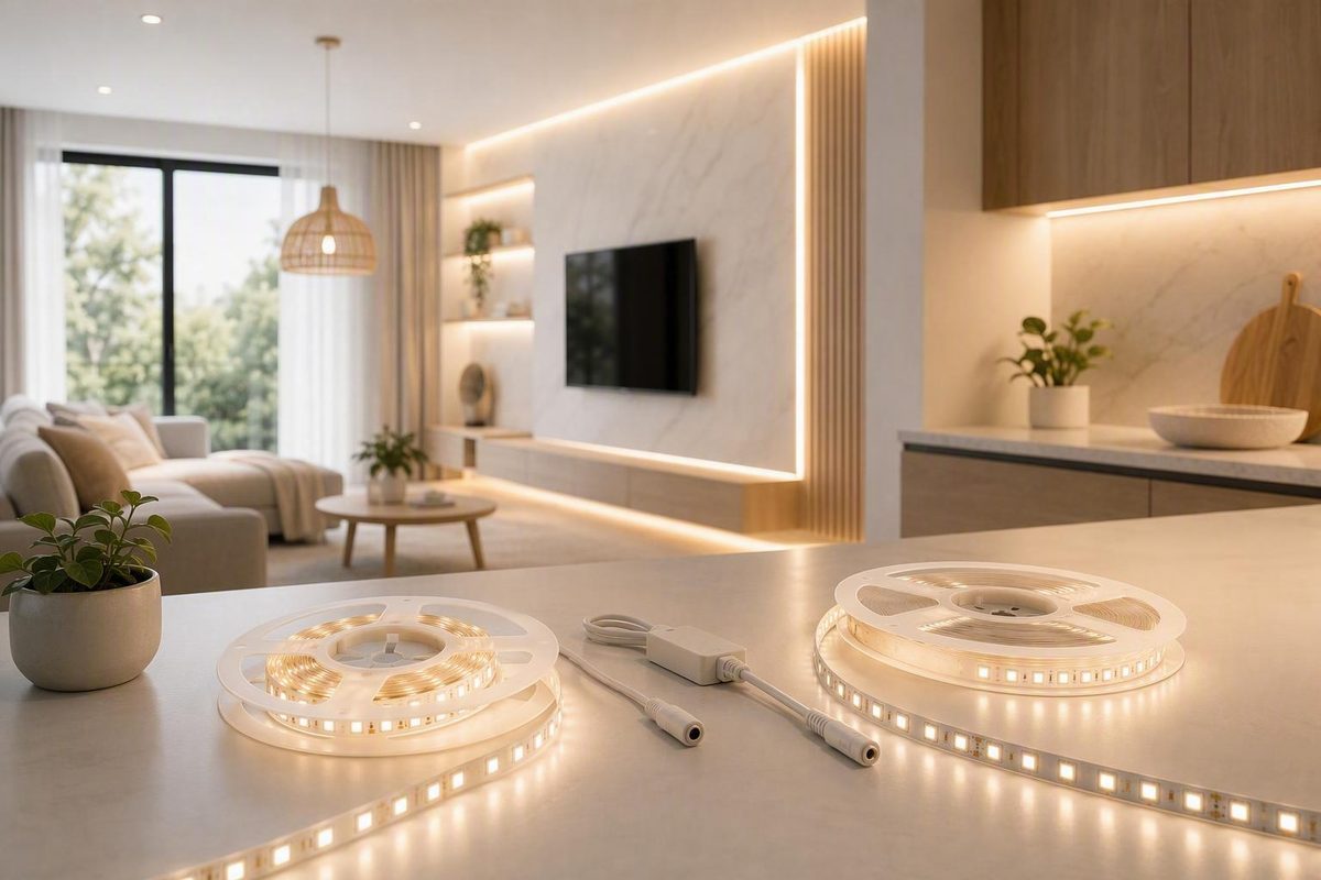
Low-voltage strip lighting looks simple on a product page: choose a reel, peel the backing, and switch it on. In practice, the reel is only one component in a small electrical and optical system.
Start with the application, not the voltage. Decide where the light will go, what it must illuminate, how it should look, and what moisture or physical exposure it will face. Then map every branch and cut, choose the strip format, calculate the load, select compatible power and controls, and plan feed points around the strip’s documented maximum run.
This guide covers flexible LED tape and strip systems commonly operated at 12VDC or 24VDC. It does not cover flexible products powered directly from household line voltage.
The central rule is straightforward: every component must agree on voltage, capacity, control type, conductor arrangement, physical fit, and location rating.
Before shopping, answer six questions:
- What light output, color quality, and visual effect does the application require?
- How long is each branch, and where can power reach it?
- Does the layout favor the cut precision of 12V or the lower current of 24V?
- What are the strip’s rated power and maximum continuous run?
- Which supply, controller, connectors, wire, channels, and enclosures are compatible?
- Can every cut, connection, and component withstand its actual location?
What low-voltage strip lighting includes
A typical low-voltage LED strip system follows this path:
Household AC
    │
    ▼
Compatible power supply or LED driver
    │  12VDC or 24VDC
    ▼
Optional dimmer or controller
    │
    ▼
LED strip
The power supply converts household AC into the DC voltage required by the strip. A fixed-white installation may need only a supply and a compatible dimming arrangement. Tunable-white, RGB, RGBW, RGBCCT, and addressable systems generally add a controller between the supply and strip.
Not every flexible product sold as strip lighting is low voltage. Some products operate directly from line voltage and use different connectors, cutting rules, insulation systems, and installation methods. Do not apply 12V or 24V instructions to those products.
Common applications
Low-voltage strip lighting is sold for applications including:
- Under-cabinet task lighting
- Cove and tray-ceiling lighting
- Shelf and display illumination
- Sign and backlighting
- Railing and under-rail accents
- Landscape features
- Architectural accents
- Decorative lighting
Retail categories also distinguish among white, tunable-white, single-color, RGB, RGBW, COB, and addressable products. Channels, controls, power supplies, connectors, wire, and mounting hardware are commonly treated as separate system components rather than parts of the reel itself (LEDSupply’s low-voltage strip categories).
The reel is rarely the complete purchase
Depending on the project, the bill of materials may include:
- LED strip
- AC-to-DC power supply or driver
- Dimmer, color controller, or addressable controller
- Wall control, remote, gateway, or automation interface
- Low-voltage wire
- Distribution terminals or harnesses
- Strip-to-wire and strip-to-strip connectors
- Soldered lead assemblies
- Splitters
- Aluminum channels
- Diffusers
- End caps
- Mounting clips and hardware
- Surface-preparation materials
- Strain relief
- Suitable enclosures
- Manufacturer-approved sealing materials
“Works with 24V” does not establish complete compatibility.
Know the principal strip families
Fixed white or single color provides one color or one white color temperature. It commonly uses a two-conductor connection.
Tunable white combines warm-white and cool-white channels. A suitable controller blends them to adjust the apparent color temperature.
RGB combines red, green, and blue channels for colored effects. If usable white light matters, evaluate the actual mixed-white appearance rather than assuming it will perform like a dedicated white channel.
RGBW adds a separate white channel. RGBCCT adds separate warm- and cool-white channels, expanding control options while increasing the number of connections and controller channels.
Addressable strip incorporates control electronics so individual pixels or groups can show different colors. Its controller, data arrangement, power distribution, and connection requirements differ from those of ordinary analog strip.
COB or FCOB describes a construction style intended to create a more continuous-looking line of light. It is not a voltage class or control protocol.
Low voltage does not mean risk-free
Low-voltage circuits can carry substantial current. Equipment ratings and the applicable installation rules still matter.
In the United States, vendor installation guidance identifies NEC Article 725 and the local Authority Having Jurisdiction as relevant considerations for some low-voltage strip installations. That guidance is not a substitute for the adopted code, product listing, permit requirements, or a jurisdiction-specific determination (aspectLED’s electrician guide).
Keep panel work, new line-voltage circuits, and other regulated mains work outside casual DIY instructions. LED Lighting Zone’s safety notice directs panel work to an electrician, while local rules may require qualified electrical work in additional circumstances (LED Lighting Zone terms and safety notice).
Choose 12V or 24V from the layout—not from a universal rule
Neither voltage is universally better. For many short installations, either can work when the strip, supply, controller, wiring, and accessories match. The practical comparison begins with current.
Electrical power is approximately:
Power (W) = Voltage (V) × Current (A)
Rearranged:
Current (A) = Power (W) ÷ Voltage (V)
For the same 48W load:
At 12V: 48W ÷ 12V = 4A
At 24V: 48W ÷ 24V = 2A
At equal wattage, doubling the voltage halves the current. Waveform Lighting uses this 48W comparison and also documents different cut intervals and maximum runs for its corresponding 12V and 24V products (Waveform Lighting’s 12V-versus-24V explanation).
Lower current can reduce losses in the same feed wires, strip conductors, connectors, and joints. That often makes 24V worth considering for long coves, larger installations, substantial supply-to-strip cable distances, or layouts with several branches.
Many 12V products, by contrast, have shorter cut intervals. That can help when a strip must stop close to the edge of a cabinet, display, shelf, stair detail, or compartment. Twelve-volt products may also fit vehicle-based systems, but nominal voltage alone does not establish suitability for a particular vehicle or marine electrical environment.
12V-versus-24V decision table
| Project layout | Usually worth considering | Why | Verify before choosing |
|---|---|---|---|
| Short cabinet or display run | 12V or 24V | Either may work well over a short distance | Cut interval, supply location, connector size |
| Precision-fit shelves or compartments | Often 12V | Shorter cut segments are available in many product families | Actual marked cut spacing |
| Vehicle-based installation | Often 12V | Nominal voltage may simplify component selection | Permitted input range and product suitability |
| Long cove | Often 24V | Lower current can ease distribution losses | Maximum run, watts per length, feed layout |
| Architectural accent | Often 24V | Useful for longer branches or higher total power | Control compatibility and branch design |
| Multi-branch installation | Often 24V, but layout decides | Lower aggregate current may simplify distribution | Supply, controller, connector, and branch ratings |
This table is a screening tool, not a substitute for the exact data sheet. A short 24V strip may be the best physical and visual fit. A specialized 12V product may allow a longer run than an unrelated 24V product.
What voltage does not tell you
Voltage alone does not establish:
- Brightness
- Lumens per watt
- Color rendering
- Color-temperature consistency
- LED density
- Dot visibility
- Operating temperature
- Dimming quality
- Service life
Those results depend on strip architecture, component quality, power density, thermal conditions, optics, controls, and installation.
Maximum run and cut spacing are also product-specific. Waveform’s comparison, for example, gives 16-foot and 33-foot maximum runs and 1-inch and 2-inch cut intervals for its cited 12V and 24V products. Those figures describe those product versions, not all strips.
Never cross-connect voltages
A 12V strip requires an appropriate 12V output; a 24V strip requires an appropriate 24V output. Excessive voltage may damage the strip, while an output below the rated voltage may produce incorrect or unreliable operation.
Controllers, dimmers, amplifiers, and electronic connectors may support one voltage or a stated range. Verify every label and data sheet rather than assuming that all “low-voltage” components are interchangeable.
Select the strip by light quality, controls, and physical fit
Treat voltage and visual performance as separate decisions. A 24V label does not reveal whether the strip has the output, color quality, or appearance required for a countertop.
Start with the light you need
Evaluate:
- Lumen output: How much light does the strip produce?
- Power density: What are the rated watts per foot or meter?
- Color temperature: Should the light appear warm, neutral, cool, or adjustable?
- Color rendering: How should food, finishes, merchandise, and skin tones appear?
- LED or chip density: How closely spaced are the emitting points?
- Diffusion: Will a lens reduce output or improve visual continuity?
- Glare control: Can users see the strip directly or in a reflective finish?
- Dimming: Does the system need smooth low-level operation?
- Color consistency: Must separate reels or zones match visually?
For primary or task illumination, use current photometric data for the intended assembly where available. Do not rely on an unsupported universal lumen or CRI threshold, and do not assume bare-strip output will equal delivered light after recessing, diffusion, or indirect aiming.
Match strip family to the job
| Need | Family to investigate | Main tradeoff |
|---|---|---|
| One consistent white | Fixed white | Simple controls, no color-temperature adjustment |
| Adjustable white ambience | Tunable white | More channels and a compatible controller |
| Colored decorative effects | RGB | Mixed white must be evaluated for the application |
| Color plus dedicated white | RGBW | More conductors and controller channels |
| Color plus adjustable white | RGBCCT | Broad control with greater system complexity |
| Pixel or chasing effects | Addressable | Specialized controller, signal, and power planning |
| Visually continuous line | COB/FCOB or dense strip with suitable optics | Final appearance still depends on geometry |
In one vendor’s product family, single-color strip uses two conductors, tunable white three, RGB four, and RGBW five. These are product-family examples, not universal pinouts; verify the selected strip’s labels, common-conductor arrangement, and controller requirements.
SMD versus COB or FCOB
Individual points may remain visible depending on package spacing, output, channel depth, diffuser opacity, viewing angle, and nearby reflections.
The final appearance still depends on:
- Chip density
- Channel depth
- Diffuser opacity
- Strip-to-diffuser distance
- Brightness
- Viewing distance and angle
- Reflections from surrounding finishes
Mock up a short sample in the actual channel before buying the full project quantity.
Check physical fit before electrical purchase
Record:
- Bare strip width
- Width after any sleeve or coating
- Aluminum-channel interior width
- Connector-body width and height
- Diffuser clearance
- End-cap and cable-exit space
- Marked cut interval
- Documented bend direction
- Corner orientation
- Lead-wire exit
- Access for future replacement
A strip may fit a channel while its clip connector does not. A connector may fit the open channel but prevent the diffuser from closing. A cut interval may leave a dark gap at a cabinet end. A strip intended to bend in one plane may not follow the corner shown in the layout.
Application matrix
| Application | Priorities |
|---|---|
| Countertop task lighting | Deliberate output, color quality, glare shielding, even distribution, dimming |
| Cove lighting | Uniformity, run planning, concealment, feed access, reflected output |
| Shelf or display | Cut precision, compact connections, color quality, low profile |
| Sign or backlighting | Spacing, diffusion depth, uniformity, service access |
| Railing | Physical protection, cut layout, concealed connections, environmental suitability |
| Landscape accent | Location restrictions, drainage, sealing, serviceable power placement |
| Decorative color | Controller capability, effects, channel count, signal requirements |
| Visible linear accent | Dot control, channel geometry, diffuser choice, finish quality |
Calculate the load and match the power supply
Power-supply sizing starts with installed strip length—not reel count, room size, or the supply bundled with an unrelated controller.
Step 1: Calculate every branch
Use the strip’s rated power per unit length:
Branch watts = Rated watts per foot × Installed feet
or:
Branch watts = Rated watts per meter × Installed meters
Then add every branch expected to operate from the supply:
Total strip watts = Branch 1 watts + Branch 2 watts + Branch 3 watts + …
Do not mix feet and meters. Include all installed segments, including short returns and offcuts that remain connected.
For multichannel or addressable products, use the manufacturer’s stated design condition. Demand may vary with color, brightness, programming, and controller operation.
Step 2: Calculate current
Current (A) = Total watts ÷ System voltage
For a 48W load:
| System voltage | Calculation | Nominal current |
|---|---|---|
| 12V | 48W ÷ 12V | 4A |
| 24V | 48W ÷ 24V | 2A |
This is the nominal load calculation before accounting for manufacturer instructions, controller consumption, cable loss, ambient limits, or any required planning margin.
Step 3: Choose the correct supply type and capacity
Ordinary 12V and 24V tape systems commonly use a constant-voltage supply whose output matches the strip’s rated voltage. Select capacity above the calculated load in accordance with the strip and supply documentation (LEDSupply’s power and wiring guide).
Some vendor guides recommend operating at no more than 80% of supply capacity. Treat that as manufacturer or vendor guidance where stated, not as a universal electrical-code rule.
For a 48W load, therefore, do not automatically declare one particular supply size correct. Review the available ratings and instructions, then choose a model with adequate capacity under the actual installation conditions.
Step 4: Check more than wattage
Verify:
- Output voltage: Matches the strip
- Output type: Constant voltage unless the chosen strip requires something else
- Input method: Cord-and-plug or hardwired
- Input rating: Appropriate for the premises
- Dimming method: Compatible with the wall control or low-voltage controller
- Controller input voltage: Compatible with the supply
- Controller total capacity: Adequate for all connected strip
- Per-channel capacity: Adequate for each color or white channel
- Location rating: Suitable for the installation environment
- Ambient and ventilation limits: Suitable for the mounting space
- Terminal suitability: Compatible with the conductor sizes and connection count
- Service access: Reachable for testing or replacement
“Dimmable” does not identify a complete control method. A supply designed for input-side dimming and a controller that performs low-voltage PWM dimming are different arrangements. Confirm that the supply, dimmer, controller, and strip are intended to work together.
One supply can serve multiple branches—with limits
Parallel branches may share one supply when:
- The supply voltage matches every branch.
- Total simultaneous demand remains within supply capacity.
- The dimmer or controller can carry the total load.
- Every controller channel remains within its rating.
- Distribution terminals and connectors are suitable.
- Conductors are selected for their current and distance.
- Applicable circuit-protection requirements are addressed.
- Loaded voltage remains acceptable at each branch.
Parallel branches are generally preferable to extending one strip through another because each branch starts from a distribution point rather than relying on the preceding strip’s conductors. Branch results can still differ when wire length, conductor size, connectors, or loads differ.
The evidence does not support a universal connector-current, fuse-sizing, or wire-gauge chart. Determine those items from the actual current, conductor length, acceptable voltage drop, installation conditions, equipment documentation, and applicable electrical requirements.
Plan run length, wiring, and voltage drop before installation
Voltage drop is voltage lost as current flows through resistance. In a strip-light system, relevant resistance can be present in:
- Flexible-circuit traces
- Feed wires
- Connector contacts
- Solder joints
- Terminal blocks
- Controller output paths
- Splices and distribution points
A common visible symptom is declining brightness toward the far end. Multichannel strips may also show uneven color as available voltage declines. Manufacturer wiring guidance similarly identifies resistance, run length, and maximum-run limits as central considerations (GL LED’s wiring guide).
The manufacturer’s maximum continuous run is the starting constraint. There is no universal feet-per-voltage rule: product architecture, power density, circuit-board construction, feed method, and permitted variation all matter.
Common feed arrangements
Single-end feed
Supply/controller ─────────► Strip
                             near end ======== far end
This is the simplest arrangement. Use it only when the section stays within the strip’s documented run limit and performs acceptably under load.
Center feed
Strip left ◄────── Feed point ──────► Strip right
                 Supply/controller
A center feed divides one physical line into two current paths. It may improve uniformity because current does not travel from one extreme end to the other. Use it only where the strip documentation and controller arrangement permit it, and include both sides in the total load.
Separate parallel home runs
                         ┌────────► Strip A
Supply/controller ───────┼────────► Strip B
                         └────────► Strip C
Each strip section receives a separate feed from a distribution point. This can keep every section within its documented maximum run while allowing the branches to share a suitably sized supply and controller.
The branches receive the same nominal source voltage, but their loaded input voltage may differ if cable length, conductor size, connector count, or branch demand differs.
Additional feed or power injection
Primary feed ───────────► Strip ====================
                                  ▲
                                  │ additional feed
                                  └──── compatible source/control
Power injection adds another electrical feed point to reduce local voltage drop. The supply, controller, conductors, connectors, and any required protection must still be suitable for the total connected load.
Addressable systems also require the controller and signal topology to remain valid. Follow the documentation for the selected strip and controller rather than applying an analog-strip diagram without verification.
What about feeding both ends?
Dual-end feeding is not a universal cure for long strips. Where a manufacturer permits it, the design still requires:
- Correct polarity
- Suitable conductor capacity
- A clearly defined common-source arrangement
- Compatible controller placement
- Appropriate circuit-protection planning
- Protection against connecting incompatible outputs
- Verification under load
Do not connect opposite ends to unrelated supplies unless the product and system documentation expressly provide for that arrangement.
A practical commissioning sequence
If the far end is dim or one branch behaves differently:
- De-energize and inspect labels. Confirm the supply output, controller input and output, strip voltage, polarity, and channel order.
- Inspect every connection. Look for partially seated clips, damaged pads, loose terminals, poor joints, and conductors clamped on insulation.
- Energize only for the necessary measurements. Follow the meter and equipment instructions and keep exposed line-voltage work outside DIY troubleshooting.
- Measure the loaded supply output.
- Measure each strip input. A substantial loss before the strip directs attention to the feed wire, controller, terminals, or connectors.
- Measure the far end. Compare it with the strip input under the same brightness and color condition.
- Compare branches. Check cable length, conductor size, connector count, and strip length.
- Check controller loading. Confirm total and per-channel demand remain within documented ratings.
- Investigate abnormal heat. De-energize the system before correcting a warm or discolored connection.
- Reconfigure if necessary. Shorter parallel branches, a permitted center feed, or an approved additional feed may be better than extending a marginal chain.
Choose wire by calculation and documented requirements rather than a generic table. Relevant inputs include branch current, round-trip distance, acceptable voltage drop, conductor material, ambient conditions, installation method, terminal compatibility, and applicable ampacity rules.
Cut, connect, mount, and cool the strip
Physical planning should happen before cutting. An electrically compatible system can still fail as a project if the final segment overhangs a cabinet, a connector will not fit the channel, or a protected strip cannot follow the intended corner.
Cut only at designated marks
Flexible strip is divided into electrical segments. Cut only at the manufacturer’s printed line or copper-pad location. Cutting elsewhere can disable part of the segment or leave no suitable termination point.
Cut intervals vary by product. One RDI railing-strip listing, for example, gives designated cutting locations every 2 inches even though another phrase on the page says the strip can be cut to “any length.” The marked intervals are the useful layout instruction for that product (DeckExpressions’ RDI strip listing).
Before ordering, lay out each cabinet, shelf, railing section, or corner in increments of the actual cut interval. Include connector gaps, channel breaks, and end caps.
Quick connectors versus soldered joints
Cut sections may be reconnected using compatible solderless connectors or properly made soldered leads.
Solderless connectors can provide:
- Faster assembly
- Easier field replacement
- Convenient testing and reconfiguration
- Installation without soldering equipment
Soldered joints can provide:
- A lower-profile connection
- Flexible lead routing
- Better fit in narrow channels
- Direct attachment to the copper pads
Neither method is universally reliable. Verify:
- Strip width
- Pad arrangement
- Conductor count
- Polarity and common-conductor topology
- Connector or joint capacity
- Compatibility with coatings or sleeves
- Channel clearance
- Strain relief
- Environmental suitability
As practitioner guidance rather than a code rule, avoid placing an added feed and a strip-to-strip splice on the same small or compromised pad when separate full pads are available. This reduces mechanical congestion at one connection point.
Adhesive backing is not a universal mounting system
Mounting performance depends on:
- Surface cleanliness
- Surface material and texture
- Paint condition
- Temperature
- Heat generated by the strip
- Moisture
- Gravity and mounting orientation
- Flexing or vibration
- Product storage and age
Dry-fit first. Prepare the surface according to the strip or tape instructions. Use channels, clips, or another approved retention method where adhesive backing alone is unsuitable.
What aluminum channels can and cannot do
An aluminum channel may help with:
- Straight and secure mounting
- Physical protection
- Cleaner appearance
- Diffuser retention
- Glare and dot control
- Heat spreading
- Replacement access in some assemblies
It cannot correct an overloaded supply, an undersized feed, an excessive run, an incompatible controller, or a poor joint.
Dry-fit checklist
Before removing adhesive liner or making final joints, confirm:
- [ ] The strip fits inside the channel.
- [ ] The protected strip’s outside width fits, not merely the bare-board width.
- [ ] The diffuser closes above the strip and connectors.
- [ ] Connector bodies fit at joints.
- [ ] Lead wires can exit without sharp pinching.
- [ ] Corners follow the documented bend direction.
- [ ] Every cut lands at a marked point.
- [ ] Feed points remain accessible.
- [ ] End caps fit with the cable exit.
- [ ] The power supply and controller remain serviceable.
- [ ] The mock-up has acceptable dotting, glare, color, and brightness.
Match the complete installation to moisture and outdoor exposure
An IP label is not blanket approval for every installation carrying the same number. Product documentation, cut treatment, connector construction, orientation, enclosures, and stated restrictions still control the intended use.
Use IP20, IP65, IP67, and IP68 as product categories to investigate—not as automatic permission for a location. A retailer may group indoor strip under IP20, outdoor products under IP65–IP67, and some specialized products under IP68, but those category labels do not establish identical suitability across every model.
Location matrix
| Location | Category to investigate | Questions that still need answers |
|---|---|---|
| Dry interior | Often IP20 | Is there spray, condensation, grease, cleaning exposure, or contact risk? |
| Splash-prone interior | Often IP65 or another product documented for the exposure | Where can water strike, and how are cut ends and leads treated? |
| Covered exterior | Often IP65 or IP67 | Can wind-driven rain reach it? Can condensation collect? |
| Exposed exterior | Often IP67 or a product expressly documented for the location | Are UV exposure, drainage, orientation, connections, and entries addressed? |
| Possible temporary immersion | Only a product expressly documented for the actual conditions | What depth, duration, medium, and installation restrictions apply? |
| Continuous submersion | An IP68 product expressly documented for the depth, duration, and medium | Are the strip, joints, cables, controls, and installation method all approved? |
The matrix is a shopping screen, not an approval table. For broader context, see this guide to water-resistant LED strip IP ratings, then verify the selected product’s current manufacturer documentation.
One seller’s IP67 landscape strip illustrates why that verification matters: the seller expressly says its product is not submersible, requires additional weatherproofing accessories at cut joints, and imposes placement restrictions. That cited product operates at a seller-stated 12V AC/DC and is used here only as an environmental-label example—not as a general example of a compatible 12VDC strip system (Lumiere Lighting’s IP67 landscape-strip listing).
Protection depends on the complete installation
Environmental suitability depends on more than the reel:
- Factory strip construction
- Cut ends
- Splices
- Connector bodies
- Cable entries
- Controller enclosure
- Power-supply enclosure
- Junction and distribution enclosures
- Mounting orientation
- Drainage
- Condensation
- Mechanical strain
- UV or chemical exposure
Cutting or opening a protected strip changes the factory-supplied enclosure at that point. Treat the resulting end or joint according to the exact product instructions.
Field sealing is not automatically a tested rating
Manufacturer-approved end caps, sealed connectors, silicone, potting compounds, or adhesive-lined heat-shrink may form part of an acceptable installation.
Follow the approved process and verify:
- Material compatibility
- Surface preparation
- Required overlap
- Cable diameter
- Cure time
- Mounting orientation
- Inspection requirements
Where a documented environmental rating is required, obtain information that covers the completed connection method—not only the uncut reel.
Remember the thermal and physical tradeoffs
Follow the selected product’s mounting and ambient-temperature instructions. Do not assume that adding an aluminum channel validates a sealed strip for an undocumented enclosure or operating condition.
The driver, controller, connectors, distribution enclosure, and cable entries also need to suit their locations. Keep line-voltage work near water outside casual DIY instructions.
Use a system checklist before buying or energizing anything
The best time to find an incompatible connector, missing controller, impossible cut interval, or unsuitable enclosure is before ordering.
Pre-purchase worksheet
Application and layout
| Field | Project value |
|---|---|
| Application | |
| Exact location | |
| Total installed length | |
| Branch 1 length | |
| Branch 2 length | |
| Additional branch lengths | |
| Selected voltage: 12V or 24V | |
| Rated watts per foot or meter | |
| Calculated total watts | |
| Calculated current | |
| Product maximum continuous run | |
| Cut interval | |
| Feed method | |
| Supply-to-strip cable distance |
Sketch the installed system:
AC source → supply → dimmer/controller → distribution → branch A
                                               ├──────→ branch B
                                               └──────→ branch C
Mark every cut, connector, splice, feed point, corner, channel break, and enclosure.
Light quality and controls
| Field | Project value |
|---|---|
| Required lumen output | |
| Color temperature | |
| CRI or other color-quality data | |
| Strip family | |
| LED or chip density | |
| SMD, COB, or FCOB | |
| Channel and diffuser | |
| Glare-control method | |
| Dimming requirement | |
| Color-control requirement | |
| Wall control, remote, app, or automation interface | |
| Current photometric data reviewed |
For task or primary illumination, test a sample against the actual finishes. Countertops, glossy backsplashes, glass shelves, and polished metal can reveal glare and individual light points that are not obvious on a product page.
Physical fit
| Field | Project value |
|---|---|
| Strip width | |
| Protected-strip outside width | |
| Channel interior dimensions | |
| Diffuser clearance | |
| Connector dimensions | |
| Bend direction | |
| Corner method | |
| Lead exit | |
| Mounting surface | |
| Secondary retention required | |
| Supply and controller service access |
Environmental suitability
| Field | Project value |
|---|---|
| Claimed IP rating | |
| Exact documented conditions | |
| Manufacturer location restrictions | |
| Cut-end treatment | |
| Joint and connector treatment | |
| Driver location rating | |
| Controller location rating | |
| Enclosure rating | |
| Cable-entry method | |
| Mounting orientation | |
| Drainage and condensation path | |
| UV, chemical, or salt exposure |
Electrical compatibility
| Field | Project value |
|---|---|
| Supply output voltage | |
| Supply wattage capacity | |
| Constant-voltage output confirmed | |
| Plug-in or hardwired input | |
| Dimming method | |
| Controller type | |
| Controller total capacity | |
| Per-channel capacity | |
| Strip polarity or pinout | |
| Conductor count | |
| Connector type and rating | |
| Wire calculation completed | |
| Circuit-protection design reviewed | |
| Accessories included with strip |
Resolve conflicting listings before purchase
Do not guess when a title, image, description, and data sheet disagree. Retail listings can conflict on voltage, length, strip type, environmental rating, or cutting information.
Use this priority:
- Current manufacturer data sheet for the exact model and revision
- Current installation instructions
- Product and certification labels
- Written manufacturer clarification
- Retail listing, only when consistent with the above
A URL containing “12V” does not prove that the selected variant is 12V. A generic image labeled COB does not override documentation identifying a model as SMD. “Cut to any length” does not override marked cut points.
Calculate total installed cost
Compare systems by complete installed cost, including:
- Strip reels and usable offcuts
- Power supply or supplies
- Dimmers and controllers
- Control interfaces
- Wire
- Distribution hardware
- Connectors and harnesses
- Channels and diffusers
- End caps
- Clips and mounting hardware
- Surface-preparation materials
- Sealing materials
- Enclosures and strain relief
- Test equipment
- Professional electrical work where required
A lower reel price can be offset by proprietary connectors, a larger controller, difficult protected-strip transitions, or unusable offcuts.
Commissioning checklist
Before permanent mounting:
- [ ] Confirm every component’s voltage.
- [ ] Verify polarity and channel order with power off.
- [ ] Check terminals for correct conductor insertion and secure clamping.
- [ ] Test each strip section before cutting where practical.
- [ ] Test every cut section before permanent mounting.
- [ ] Operate all intended colors and brightness levels.
- [ ] Measure loaded voltage at the supply output.
- [ ] Measure loaded voltage at each strip input.
- [ ] Measure far-end voltage on the longest branches.
- [ ] Compare brightness and color across branches.
- [ ] Test the complete dimming range.
- [ ] Check for flicker, controller dropout, or data errors.
- [ ] De-energize and investigate any abnormal heat.
- [ ] Confirm seals, cable entries, strain relief, orientation, and drainage.
- [ ] Verify that supplies and controllers remain accessible.
- [ ] Complete permanent mounting only after the system passes.
Frequently asked questions
Is 12V or 24V better for low-voltage strip lighting?
Neither is universally better. At equal wattage, 24V draws half the current: a 48W load is approximately 4A at 12V or 2A at 24V (Waveform Lighting’s comparison).
That often makes 24V useful for longer branches or cable distances. Twelve volts can suit compact layouts requiring short cut intervals. Choose from the actual power density, cut spacing, maximum run, feed layout, and compatible components—not voltage alone.
How do I calculate the power supply size for an LED strip?
Multiply rated watts per foot or meter by installed length, then add every branch:
Total watts = Watts per length × Installed length
Calculate current with:
Current = Total watts ÷ System voltage
Choose a supply whose output voltage matches the strip and whose capacity exceeds the calculated load under the applicable manufacturer instructions. Also verify the dimming method, controller limits, enclosure, terminals, ventilation, and service access.
Why is my LED strip dimmer at the far end?
Current flowing through resistance in strip traces, feed wires, connectors, and joints produces voltage drop. Check the documented maximum run, then compare loaded voltage at the supply, strip input, and far end.
Inspect joints and connectors, compare branch-wire lengths, and verify controller loading. The remedy may be a shorter parallel branch, a permitted center feed, or an approved additional feed—not merely a higher-wattage supply.
Can an IP67 LED strip be submerged?
Do not assume so. Product restrictions control the permitted use. The cited IP67 landscape strip expressly prohibits submersion, demonstrating why the label alone is insufficient (Lumiere Lighting’s product restrictions).
For any submerged application, use a product expressly documented for the actual depth, duration, medium, and installation method. Verify the complete system, including cut ends, joints, cables, controls, and enclosures.
Can I cut low-voltage LED strip lighting anywhere?
No. Cut only at the designated printed lines or copper-pad marks. The spacing is product-specific and should be included in the layout before ordering.
After cutting, use a compatible connector or properly made soldered lead. Match the strip width, pad arrangement, conductor count, polarity, connection capacity, and enclosure clearance. If the strip is protected against moisture, follow the manufacturer’s approved end-treatment process and do not assume that a field seal automatically retains the original IP rating.
A reliable project follows a project-first sequence: define the location and desired light, map every branch and cut, choose 12V or 24V from current and layout needs, calculate the load, select compatible power and controls, plan feeds around the specific strip’s maximum run, and verify physical and environmental details before permanent mounting.
The reel does not determine whether a low-voltage strip-lighting project succeeds. The result depends on whether the strip, supply, controls, conductors, connectors, channels, joints, and enclosures all agree.