
12V Dimmer Switch: Match the Control to the LED Circuit
Choose a 12V PWM dimmer by strip type, load current, power-supply compatibility, wiring, voltage drop and installation location.
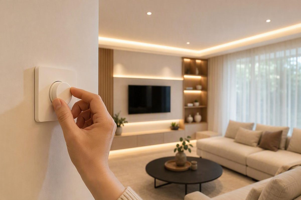
For a conventional single-color 12V LED strip, the usual choice is a 12V DC PWM dimmer installed after the power supply:
120V AC → 12V DC power supply → 12V PWM dimmer → LED strip
The dimmer must accept 12V DC, support the strip type and carry the circuit’s full current. Do not connect a low-voltage PWM dimmer directly to household power. Diode LED’s installation guide requires a compatible constant-voltage driver and explicitly warns against connecting tape light directly to high voltage (Diode LED).
First identify which “12V dimmer” you need
| Existing system | Correct control path | What to check |
|---|---|---|
| Single-color 12V strip with a standard, non-dimmable power supply | 12V supply → single-channel PWM dimmer → strip | 12V input/output, current rating, polarity |
| RGB, RGBW or tunable-white 12V strip | 12V supply → matching multichannel controller → strip | Strip protocol, channel count, common-anode/common-cathode arrangement and total/per-channel current |
| 12V strip with an AC-dimmable driver | Compatible 120V wall dimmer → dimmable driver → strip | Driver’s published phase-control and dimmer compatibility |
| Integrated 12V lamp or fixture | Only the method documented for that product | It may contain electronics that do not accept output-side PWM |
A basic one-channel dimmer cannot independently control RGB colors or tunable-white channels. Controller type must match the strip; an RGB controller used with RGBW tape, for example, cannot control the separate white channel (Super Bright LEDs).
Do not put an ordinary 120V incandescent wall dimmer between the outlet and a standard 12V power supply. AC-side dimming requires a driver specifically listed as dimmable by that method. For a standard supply, place the PWM control on its 12V output instead. Armacost gives the same placement rule: a low-voltage dimmer goes between the power supply’s low-voltage side and the lights (Armacost Lighting). For more on phase-cut controls, see what a TRIAC dimmer requires.
Size the dimmer in amps, not just watts
Calculate the installed strip load first:
Load watts = strip watts per foot × installed feet Load amps = load watts ÷ 12V
Then choose a dimmer whose 12V output-current rating is at least the calculated load, after applying any manufacturer-required channel limits, temperature derating or enclosure derating. Also keep the load within the power supply’s rating and the strip manufacturer’s maximum run length.
Examples:
| 12V strip installation | Load | Current | Minimum dimmer rating before product-specific derating |
|---|---|---|---|
| 10 ft at 3 W/ft | 30W | 2.5A | 2.5A |
| 16.4 ft at 4.8 W/m (1.46 W/ft) | about 24W | 2A | 2A |
| 16.4 ft at 14.4 W/m (4.39 W/ft) | about 72W | 6A | 6A |
Use the strip’s specified power for the length actually installed, not a guess based on LED count. If several branches dim together, add every branch. A larger-wattage 12V constant-voltage supply does not force excess power into the strip; voltage must match, while the supply and dimmer still need adequate capacity. Armacost confirms that matching output voltage and sufficient wattage are the governing power-supply checks (Armacost Lighting). Our 12V power-supply sizing guide covers the supply calculation separately.
Check these compatibility details before buying
- Voltage: The dimmer must explicitly support 12V DC. A 24V-only control is not a substitute.
- Strip type: Use one PWM channel for single-color tape and the correct multichannel controller for CCT, RGB or RGBW tape.
- Current limits: Check both total output and per-channel limits. Connector limits may be lower than the controller’s headline rating.
- Control style: Decide among a rotary knob, touch control, wired wall station, RF remote, Bluetooth/Wi-Fi controller or sensor. A remote and receiver must be designed to pair with each other.
- Location rating: A dry-location dimmer does not become suitable outdoors because the strip is waterproof. Protect or specify the driver, control, connectors and enclosure for the actual environment.
- Wiring and polarity: Connect supply positive and negative to the dimmer input, then dimmer output to the strip. Follow the marked polarity; reversed polarity or a poor connector can prevent operation. Diode LED advises checking all polarities and securing connections before energizing the system (Diode LED).
PWM is well suited to ordinary constant-voltage LED tape because it switches the output rapidly rather than trying to dim by simply lowering the DC voltage. Mean Well identifies output PWM as its preferred method for dimming resistor-based LED strips (Mean Well). That does not make every dimmer compatible: poor PWM frequency or incompatible electronics can still produce flicker, buzz, limited low-end range or camera banding.
Wire and test it in the right order
With power disconnected, wire power supply output → dimmer input → dimmer output → strip, observing polarity and the product diagram. Use wire sized for the current and distance; voltage drop can make the far end dimmer or warmer in color. Diode LED specifically says wire selection must account for voltage drop, amperage, location rating and whether the cable is installed in a wall (Diode LED).
Test the complete intended load at full brightness and through the whole dimming range before hiding wiring, closing channels or bonding the strip permanently. If the supply repeatedly cycles, disconnect power and recheck load and connections: an overloaded driver can enter a repeating auto-reset cycle (Diode LED). Keep mains terminations and hardwired driver installation within the product instructions and applicable electrical rules; the 12V label on the output does not make the driver’s 120V input side low voltage.