
LED Dimming: Match Your Strip, Driver and Dimmer
Compare PWM, phase-cut and 0–10 V LED dimming, calculate strip load, and check compatibility, low-end flicker, overload and voltage drop before installation.
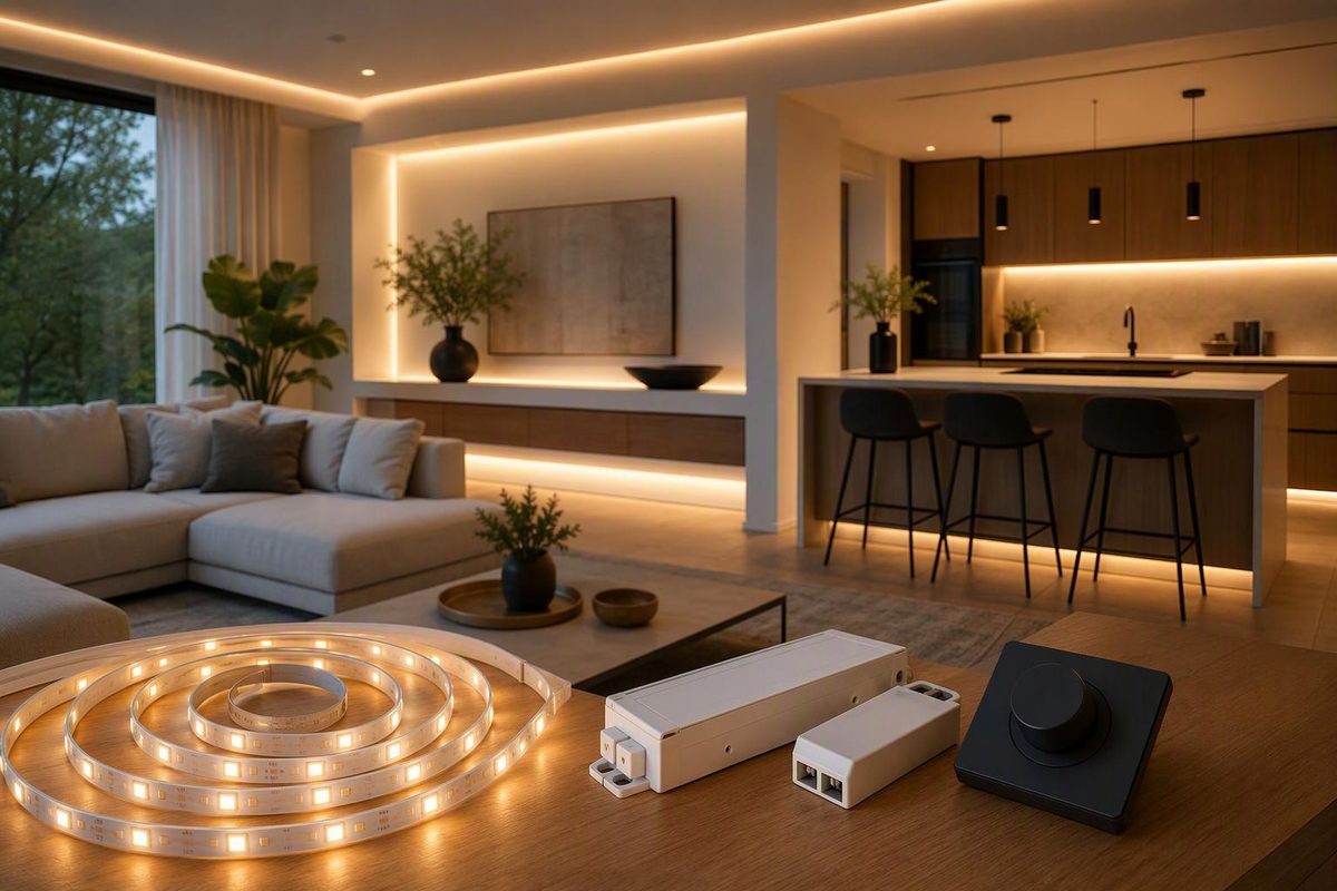
For a conventional single-color 12 V or 24 V constant-voltage LED strip, use either a compatible low-voltage PWM dimmer after the power supply or a dimmable driver controlled through its documented input. A mains wall dimmer goes before a driver specifically designed for that dimming method—not directly on the strip. Size the supply and controller for full brightness, even if you usually run the lights dimmed.
Enter your strip length, watts per metre and voltage to calculate the full-brightness load.
Full-Brightness Strip Load
5 m × 12 W/m at 24 V
Check these against the driver's capacity after required derating and the controller's W and A limits. This is not a compatibility check or a recommended supply rating.
For conventional single-color constant-voltage tape only. Use metres and W/m, not feet or W/ft.
Source: article load formulas and worked example; component limits must come from the exact model's documentation. Without JavaScript, the worked example remains visible.
“Dimmable” is only the starting point. The strip voltage, driver output, control method and connected load must agree. Diode LED’s tape-light installation guide illustrates output-side PWM and mains-side dimming arrangements and requires compatible components throughout.
Match the Control to the Driver
Read the strip, driver and dimmer labels before buying a replacement. Record the exact model numbers, not just the brand.
| Dimming Arrangement | Where It Acts | What Must Match |
|---|---|---|
| Low-voltage PWM | Between supply and strip | DC voltage, PWM compatibility, load rating and strip type |
| Phase-cut wall dimmer | Driver’s mains input | Approved pairing, phase method and load limits |
| 0–10 V control | Separate driver control terminals | Electrical interface, polarity, signal-current capacity and off behavior |
These are different circuit arrangements, not interchangeable switches. Follow the manufacturer’s system diagram for the connection path. For 0–10 V systems, Lutron’s application note explains why matching interface labels alone does not establish compatibility.
PWM Controls Output Without Changing the Specified Voltage
PWM means pulse-width modulation. It reduces average output by changing the proportion of time the LEDs are powered during each switching cycle. It is not an instruction to turn down a 24 V supply’s voltage adjustment. MEAN WELL’s PWM driver specification describes dimming by varying output-current duty cycle.
For an inline PWM arrangement, check that the supply explicitly supports the controller. Diode LED’s REIGN specification, for example, requires matching driver and fixture voltages and a constant-voltage driver compatible with PWM controls.
The load calculations here apply to ordinary constant-voltage tape. If the light specifies a regulated current in mA, identify the required driver first; see constant-voltage versus constant-current supplies.
Phase-Cut Dimming Requires an Approved Driver Pairing
A phase-cut wall dimmer controls the driver’s AC input. Check the driver’s approved controls and phase requirements rather than assuming any LED-rated dimmer will work. Lutron advises consulting the lighting manufacturer for the preferred phase method in its Maestro PRO troubleshooting guide.
For the wall-control details, use the TRIAC dimmer compatibility guide.
0–10 V Dimming May Need Separate On/Off Switching
The control signal tells the driver what light level to produce; it is not the strip’s power feed. Verify whether the driver dims to off or stops at a minimum light level, and whether the system requires a relay for on/off control.
Also match source/sink roles: one device supplies the signal current and the other accepts it. The Lutron application note above explains these driver-dependent requirements, including signal-current capacity and switching behavior.
Size Every Component for Full Brightness
Load in W equals installed length multiplied by rated W per unit length; current in A equals load in W divided by voltage in V. Keep the length units consistent: a rating in W/m needs a length in metres.
For example, 5 m of tape rated at 12 W/m draws a nominal 60 W. At 24 V, that is 2.5 A; an equivalent 60 W load at 12 V draws 5 A. These calculations establish nominal strip load, not a recommended driver rating or proof of dimmer compatibility.
Check the available driver capacity after required derating, any documented minimum load for dimming, and the controller’s total and per-channel limits where applicable. Connector and cable current ratings must also cover the connected load. Diode LED’s installation guide directs installers to product-specific load ratings, derating and minimum-load requirements; do not borrow one model’s limits for another.
Do not assume a dimmer’s wattage allowance doubles at 24 V. The REIGN family’s 2020 specification, revision 4.0, for example, lists the same 100 W maximum at 12 V and 24 V, with different current limits. That is a model-family example, not a universal dimmer rule. Read both W and A ratings in the current documentation for the actual model. For a low-voltage control checklist, see choosing a 12 V dimmer.
Next, check cable distance and the strip’s maximum run length. Voltage drop depends on supply voltage, wire length, wire gauge and load; excessive drop can produce uneven brightness or color along the strip. Use the product’s wiring chart rather than borrowing another strip’s run limit. Diode LED explains these factors in its voltage-drop guide.
There is no universal minimum dimming level or driver headroom percentage supplied by the cited guidance here. Use the limits documented for the components you intend to install.
Use the Flicker Pattern to Choose the First Check
A symptom points to a check; it does not prove a component has failed.
| Symptom | First Check |
|---|---|
| Flicker or dropout near minimum brightness | Supported low-end range and available low-end trim |
| Flicker or buzzing across much of the range | Exact dimmer/driver compatibility and required phase method |
| Entire strip repeatedly switches on and off | Driver overload and connected full-output load |
| Far end stays dimmer than the beginning | Strip run limit, feed-cable voltage drop and connections |
Lutron’s Caséta troubleshooting guidance recommends low-end adjustment for flicker or dropout at minimum settings and compatibility checks for buzzing throughout the range. These are checks for the controls covered by that guidance, not evidence that every dimmer has the same adjustment. Diode LED’s tape-light guide identifies overload-related cycling, loose connections and excessive run length as separate checks.
If a compatible system is stable except at the bottom of its range and its dimmer offers low-end trim, follow the exact manual to raise the minimum level until the light remains stable. Then switch it off and restart at that setting, as Lutron specifies in its Maestro PRO guide. Low-end trim sacrifices some dimming depth; it does not repair an overloaded driver or incorrect wiring.
A consistently dim far end deserves a wiring and run-length check before a dimmer replacement. Likewise, repeated whole-strip cycling calls for checking the full-output load against the driver’s documented capacity rather than treating the symptom as a low-end adjustment problem.
Test the Complete Circuit Before Concealing It
Pre-test the intended strip length, controller, supply and feed cables before removing adhesive backing or closing channels. Keep the tape uncoiled while powered. The Diode LED installation guide calls for system testing before permanent installation and warns against powering tightly coiled tape.
Check full brightness, intermediate settings, the lowest stable setting and restart from off. Use the actual installation components: a successful test with a different supply or shorter strip does not establish that the intended arrangement meets its load and wiring limits.
Disconnect power before changing connections. Low voltage does not automatically mean DIY: the cited Diode LED tape and REIGN instructions specify qualified, licensed installation. Keep DIY work to low-voltage tasks permitted by the product instructions and local rules; mains dimmer replacement, hardwired driver connections and panel work belong with a qualified electrician.