
SPDT Toggle Switch: Terminals, Functions and LED Wiring
Identify SPDT terminals, choose ON-ON or ON-OFF-ON action, calculate DC load, and wire one 12V or 24V LED supply to two selectable loads.
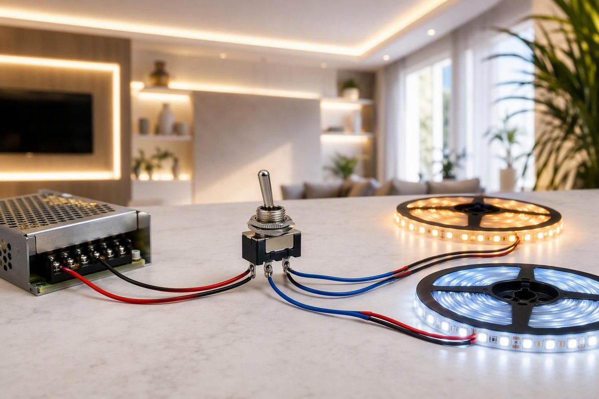
An SPDT toggle switch routes one common terminal to either of two switched terminals. For low-voltage LED lighting, choose an ON-ON model to select load A or load B, or an ON-OFF-ON model when the center position must turn both off.
SPDT means single pole, double throw:
- Single pole: one circuit is switched.
- Double throw: the common can connect to either of two terminals.
- Typical terminal count: three—common, throw A and throw B.
The letters do not specify the number of lever positions or whether the action is maintained or momentary. NKK distinguishes these terms explicitly: an SPDT switch can have two positions (ON-ON) or three positions (ON-OFF-ON) (NKK switch fundamentals).
Choose the required switch function
| Marking | Lever positions | What it does | Typical LED use |
|---|---|---|---|
| ON-ON | 2 | Common connects to A or B | Select either of two strips, zones or control inputs |
| ON-OFF-ON | 3 | A, disconnected, or B | Select strip A, all off, or strip B |
| (ON)-OFF-(ON) | 3 | Spring return from both outer positions | Brief test, trigger or control input—not maintained lighting |
| ON-(ON) | 2 | One maintained and one spring-return position | Specialized control input |
Parentheses identify a momentary position, while plain “ON” identifies a maintained or latching position. “OFF” means the actuator stops in a position with no electrical connection (DigiKey’s switch-function guide).
An ON-ON switch does not provide an all-off state. Although an SPDT device can serve as a basic on/off switch by leaving one throw unused, an SPST ON-OFF switch is usually clearer for that job.
Identify the terminals before wiring
Do not assume the center lug is common or that the toggle points toward the active terminal. Terminal arrangements vary.
- Disconnect all power.
- Find the manufacturer’s terminal diagram for the exact part number.
- If the switch is unmarked, set a multimeter to continuity.
- Test all three terminal pairs in each lever position.
- The terminal that connects alternately to each of the other two is common.
In one current C&K T-series SPDT example, terminal 2 is common: one position connects 2–3 and the other connects 2–1. The ON-OFF-ON version opens the contacts in the middle. This is an example, not a universal pinout; consult the exact switch datasheet (C&K T-series datasheet).
Illuminated toggles can have extra lamp terminals. Confirm the lamp voltage, polarity and wiring diagram rather than treating every lug as part of the SPDT contact set.
Basic 12V or 24V LED selector wiring
This arrangement applies to two constant-voltage, single-color LED loads that use the same supply voltage:
Power-supply +  ── fuse ── COM
                           ├── Throw A ── LED load A +
                           └── Throw B ── LED load B +

Power-supply −  ──────────────────────── both LED load − terminals
The fuse shown is schematic: select its rating and placement together with the power supply, conductor sizes and any required branch protection.
Use ON-ON for A/B selection or ON-OFF-ON for A/off/B. Both LED products must match the power-supply output voltage. A 12V strip requires a 12V constant-voltage supply; a 24V strip requires 24V. See the system checks in Low Voltage Strip Lighting: 12V vs 24V Buying Guide.
This circuit selects one positive branch. It does not control the loads independently or normally turn both on together. It also cannot reverse both conductors; polarity reversal requires a suitably wired DPDT switch, not an SPDT switch.
If a PWM dimmer or controller is present, follow its documented wiring. Do not casually place a selector between controller output channels: RGB, RGBW and addressable strips assign different functions to their conductors, and cross-connections can damage equipment. For a single-color circuit, switching the dimmer’s supply input or using a documented control input may be cleaner. The dimmer must still match the strip voltage and current; see 12V Dimmer Switch: Match the Control to the LED Circuit.
Size the switch for the DC load
Calculate current from the larger of the two selectable loads:
Current (A) = load power (W) ÷ supply voltage (V)
A 60W load draws approximately:
- 5A at 12V
- 2.5A at 24V
Choose a switch whose datasheet explicitly rates the exact part for at least that current at the circuit’s DC voltage. Do not treat a prominent AC rating as an equivalent DC rating. Carling, for example, lists some toggle families as AC-only and others with stated AC/DC or 12/24V ratings (Carling toggle-switch range).
“SPDT” alone says nothing about electrical capacity. In the C&K T-series example, power-contact versions are rated either 2A or 3A at 28V DC depending on the model and contact material; gold low-level contacts instead have a 0.4VA maximum rating at up to 20V AC or DC (C&K T-series datasheet). Read the complete ordering code, not just the family name.
Also verify:
- maintained versus momentary action;
- terminal style and accepted wire size;
- panel-hole diameter and allowable panel thickness;
- environmental or enclosure rating;
- conductor and fuse sizing;
- whether the manufacturer’s rating covers the intended switching duty.
The switch is sized for the largest load it can select, but the power supply must be sized for every load that can operate simultaneously elsewhere in the system. For a load above the toggle’s rating, use the switch as a low-current control for a correctly rated relay or electronic power stage rather than passing the full LED current through it.
Keep this arrangement on the isolated 12V or 24V output side of a suitable LED power supply. Household mains switching requires appropriately listed devices, enclosures, grounding and wiring methods; that work belongs with a qualified electrician.