
LED Strip Lights for Stairs Need a Coordinated System
A 48W load is about 4A at 12V and 2A at 24V. Use cut interval, cable distance and controller compatibility to choose a setup that fits.
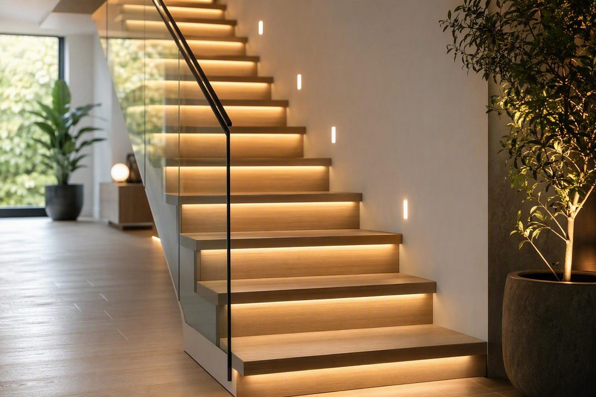
Plan a stair-lighting system that fits, powers, and controls correctly.
LED strip lights for stairs should be purchased as a coordinated system, not as a reel of tape light with accessories added later. Placement affects glare and cable routing. Strip voltage affects current and cut precision. Wiring topology affects voltage drop. Controls determine whether every step needs its own circuit. Channels influence appearance, mounting, and replacement access.
Begin by mapping the staircase and deciding what the lighting should do. Then verify that the strip, profile, diffuser, driver, controller, sensors, connectors, and wiring fit both the staircase and one another. This avoids selecting an attractive strip or channel only to discover that it cannot be cut to the required lengths, fit the profile, work with the controller, or reach the power source without uneven output.
This is a preliminary planning and buying guide for low-voltage LED systems. It does not establish compliance with local building, electrical, accessibility, egress, emergency-lighting, or structural requirements.
Start With the Staircase, Not the Product Listing
First decide whether the strips will create a decorative glow, supplement existing staircase lighting, or provide more substantial illumination of the walking surface. That decision shapes placement, output, diffusion, and dimming.
Commercial guides often recommend lower- or medium-output strips when the LEDs sit close to the illuminated surface and are not the primary light source. Those recommendations do not establish stair-specific illuminance or code requirements. Do not treat an advertised lumen figure as proof that a design meets applicable rules.
Create a scaled sketch showing:
- Number of steps
- Illuminated width of each tread
- Required strip length on each step
- Landings and changes of direction
- Handrail and side-wall sections
- Proposed controller and driver locations
- Approximate cable distance from each step to the controller
- Distance from the controller to the driver
- Available access beneath, behind, or beside the staircase
- Likely sensor positions
- Removable access points for future service
Do not calculate cable requirements from visible stair dimensions alone. A staircase may use only a short strip on each tread while requiring a separate return cable from every step to a central controller. The electrical distance can therefore be much greater than the physical stair length.
Check access before choosing individual step lights
Individual strips beneath each tread normally need a wire exit and a route to a junction point or controller. Rear or underside access makes that easier. In one merchant-hosted account, an installer used 13 lights from a 16-light kit, ran each step back to the controller, and found that an obstruction behind one riser prevented the top step from being wired like the others. That is one installation experience, not a general standard, but it shows why access should be inspected before ordering or drilling (read the installation account).
If there is no practical rear access, consider a surface-mounted side-wall or handrail profile with an accessible cable route. It may be more visible than concealed under-tread wiring, but it can reduce the number of risers that need to be drilled and make later repairs less disruptive.
Choose individual segments or a continuous run
Individual step segments support precise positioning and step-by-step activation. Each strip can align with its tread, and a sequential controller can identify each step separately.
Continuous strips can run beneath a handrail, along a stringer, or around a side-wall feature. They simplify control because the whole run can operate as one zone. They may be more affected by cut limitations, corners, maximum feed length, and far-end voltage drop.
A third option is to divide the staircase into several short groups. Each group operates together but receives a separate parallel feed. This can be a practical compromise when individual sequencing is unnecessary but one long, end-fed strip would be electrically awkward.
Record construction and installation type
Identify whether the stairs are wood, tile, carpeted, painted, metal, masonry, or part of an outdoor assembly. The substrate affects channel selection, fasteners, adhesive choices, drilling methods, cleaning exposure, and the possibility of finish damage.
Also decide whether the installation will be:
- Surface-mounted or recessed
- Temporary or permanent
- Concealed or intentionally visible
- Indoor, damp-location, or outdoor
- Plug-in or connected through fixed electrical equipment
- Serviceable from the front, rear, underside, or an access panel
Make these decisions before routing channels or drilling cable holes. Recessing a profile is difficult to reverse, and a general lighting guide cannot determine where cutting is acceptable on a particular staircase.
Use a step-by-step measurement worksheet
| Step | Strip length | Valid cut length | Cable length to controller | Channel length | Wire exit | Sensor relationship | Access point |
|---|---|---|---|---|---|---|---|
| 1 | |||||||
| 2 | |||||||
| 3 | |||||||
| Landing |
Add a row for every step and landing. The valid-cut-length column matters: a nominal 800 mm tread does not mean the selected strip can be cut to exactly 800 mm. Record the closest usable length from the product documentation.
Build a Complete Component and Compatibility List
A typical stair-strip system may include:
- LED strip
- Aluminum channel or profile
- Diffuser
- End caps
- Voltage-matched driver or power supply
- Low-voltage wire
- Strip-to-wire connectors or soldered leads
- Splitters, terminal blocks, or other distribution hardware
- Mounting clips, screws, brackets, or suitable adhesive
- Switch, dimmer, remote, or app control
- Optional motion sensors
- Optional sequential stair controller
- Suitable enclosures and cable-entry hardware
- Tools and test equipment
These parts may be sold separately. Do not assume that a channel includes a strip or that a strip includes a driver, controller, diffuser, connectors, or mounting hardware.
Build a compatibility matrix before buying
| Item to verify | What must agree |
|---|---|
| Strip voltage | Driver output, controller input and output, dimmer, and powered accessories |
| Total strip wattage | Driver capacity and controller total capacity |
| Per-step wattage or current | Controller’s per-channel limit |
| Strip width | Internal profile opening and connector clearance |
| Strip height and coating | Channel depth and diffuser clearance |
| Cut interval | Required length for each tread or segment |
| Strip architecture | Static white, tunable white, RGB/CCT, or addressable control |
| Controller channel count | Number of separately controlled steps or zones |
| Dimming method | Driver, dimmer, controller, and strip design |
| Connector type | Strip width, pad layout, conductor count, and coating |
| Sensor type | Controller input and supported operating arrangement |
| Environmental rating | Every exposed component, not only the strip |
| Replacement strategy | Availability of compatible strips, sensors, controllers, and connectors |
Physical compatibility matters as much as electrical compatibility. A strip may fit the channel while leaving too little room for a clip-on connector. A coated strip can be thicker than its bare equivalent. A diffuser may interfere with a tall connector or poorly positioned wire exit.
Match controls to the strip architecture
Static-white strips generally use two-conductor low-voltage wiring and can be operated by a compatible switch, dimmer, relay, or stair controller.
Dim-to-warm and tunable-white strips are different. Dim-to-warm products alter their white appearance as output changes according to their design. Tunable-white strips normally require separate management of warm- and cool-white channels.
RGB/CCT strips use multiple color and white channels. The controller, connector pinout, conductor count, and output capacity must match the strip.
Addressable strips require a compatible data protocol as well as power.
Basic whole-stair system or sequential kit?
A basic whole-stair system can use a wall switch, compatible dimmer, remote, app, or simple motion sensor. All strips may turn on together as one zone or as several parallel-fed groups.
A conventional sequential system usually needs:
- A controller with enough outputs for the planned steps
- One identified circuit per step
- Compatible top and bottom sensors
- A suitable power supply
- Correctly numbered wiring
- Adequate capacity on every controller channel
- Configuration for direction, speed, delay, and shutoff behavior where supported
Verify a kit’s current manual and included parts before buying. Check the supported step count, strip length per step, sensor quantity, driver capacity, per-channel load, extension-wire length, mounting hardware, and replacement-part availability.
Do not rely on listing titles or product images when they conflict. One retailer page refers variously to kits for 10, 12, 16, and 20 stairs and is unclear whether 3000K and 6000K are separate versions or an adjustable range (review the conflicting listing).
Calculate the complete project cost
Do not compare systems by reel price alone.
| Cost category | Allowance |
|---|---|
| LED strips, including waste and test pieces | |
| Channels and diffusers | |
| End caps and corners | |
| Driver or power supply | |
| Controller and dimming hardware | |
| Sensors | |
| Wire and distribution hardware | |
| Connectors or soldering materials | |
| Enclosures and cable entries | |
| Fasteners and mounting materials | |
| Tools and consumables | |
| Shipping and taxes | |
| Professional electrical or structural input | |
| Spare replaceable components |
A low-cost strip can produce a more expensive project if it needs an unusual controller, proprietary connectors, additional power feeds, or extensive labor to accommodate its cut interval.
Compare Under-Tread, Riser, Side-Wall, Handrail, and Recessed Placement
Placement determines what users see, which surfaces receive light, and how difficult installation and replacement will be.
| Placement | Source visibility and glare | Wiring and access | Cleaning and replacement |
|---|---|---|---|
| Beneath tread lip, facing down | Usually indirect; emitters can remain out of direct view | May need a separate wire exit at each tread | Exposed to dust but often reachable from the front |
| Tread frame facing the riser | Can wash the riser; source may be visible from some angles | Depends heavily on stair construction | May collect dust and cleaning residue |
| Side wall or stringer | Can illuminate multiple steps or create a continuous line | Often easier when rear access is unavailable | Profile remains visible but can be accessible |
| Beneath handrail | Keeps hardware away from tread surfaces | Requires a route through or along the rail and wall | May be accessible, although the source can be visible from below |
| Recessed tread, riser, or wall profile | Can create a flush appearance | Requires accurate cutting and planned wire exits | Repair can be difficult if the profile is sealed in |
| Surface-mounted profile | Avoids routing a recess | Usually easier for retrofits | Profile remains visible but is generally easier to remove |
Indirect placement can keep emitters out of direct view. A diffuser and sufficiently deep channel can soften visible points, but results depend on LED spacing, strip type, channel depth, diffuser material, output, mounting distance, and viewing angle. A shallow profile with widely spaced LEDs may still show a dotted pattern through an opal cover.
It is not a guarantee against visible patterning: close viewing, shallow diffusion, high output, bends, and variations in the emitting surface can still affect appearance.
Surface-mounted versus recessed profiles
Surface mounting usually requires less cutting, but the profile, fasteners, end caps, and possibly part of the cable route remain visible.
Recessing can make the profile flush with the surrounding surface, but the recess must match the selected model. One retailer guide mentions approximately 10–12 mm only as a typical estimate and makes the actual depth dependent on the channel dimensions (see the recessed-stair guide). Do not use that range as a universal routing depth.
Before ordering a profile, verify:
- Internal opening and maximum strip width
- Profile depth and exact recess dimensions
- Diffuser clearance above the strip and connectors
- End-cap thickness
- Wire-exit location
- Straight, corner, and landing transitions
- Bend constraints
- Fastening method
- Compatibility with the substrate
- Whether the diffuser remains removable after installation
A product marketed for stair placement is not automatically load-bearing, slip-resistant, or suitable for direct tread-edge foot traffic. Those characteristics require documentation for the specific model.
Temporarily position sample lengths before drilling or applying permanent adhesive. View them while approaching from both directions, with nearby lighting on and off. Check whether emitters are visible, whether glare obscures tread edges, and whether the proposed cable exit can be concealed.
Choose the Strip by Light Quality, Cut Interval, and Control Type
Choose the strip according to the intended appearance and control behavior rather than voltage alone.
Strip categories
- Static white: One fixed white appearance with relatively simple control.
- Dim-to-warm: Changes its white appearance as it dims according to the product design.
- Tunable white: Adjusts between warmer and cooler white through a compatible multi-channel controller.
- RGB/CCT: Combines colored output with adjustable white channels.
- Conventional addressable: Supports individually controlled pixels or segments and animated effects.
- Single-color strip with a sequential controller: Uses a separate step circuit for each tread to create step-by-step activation without addressable pixels.
Choosing 24V instead of 12V does not inherently create more light.
Commercial stair-lighting guidance commonly suggests warm-to-neutral white in the 2700K to 4000K range and lower- or medium-output strips for nearby accent or supplemental lighting. These are vendor recommendations, not universal safety or code thresholds (see the vendor’s selection guidance).
Make cut interval a primary specification
Individual tread segments must end at marked cut points. Twelve-volt strips often permit shorter cuts than comparable 24V designs because their electrical segments may contain fewer LEDs. One supplier illustrates this with 50 mm intervals for a 12V design and 100 mm for a 24V design, while emphasizing a model-style comparison rather than a universal specification (compare the cut-point example).
Check the actual cut interval before purchasing. Also confirm:
- Whether cut sections can be reconnected
- Solder-pad dimensions
- Compatible connector type
- Required conductor count
- Whether cutting interrupts or changes a protective coating
- Whether the remaining end margins will look balanced
A coarse cut interval may force uneven margins at the sides of a tread even when the reel is otherwise suitable.
Consider maintenance before choosing effects
Addressable flowing effects can add:
- Protocol and controller compatibility requirements
- Data wiring or configuration
- More complex fault diagnosis
- Product-specific replacement dependencies
- Additional power-distribution considerations
- Reliance on firmware or app support in some systems
A single-color sequential system sits between the two: it adds multiple controller outputs and step wiring but avoids pixel-level strip protocols.
A practical decision tree
-
Do you want colored or animated effects? - No: consider static white, dim-to-warm, or tunable white. - Yes: consider RGB/CCT or addressable strip.
-
Must the white appearance be adjustable? - No: static white is simpler. - Yes: verify a compatible tunable-white or RGB/CCT controller and driver arrangement.
-
Should each step activate separately? - No: use whole-stair control or grouped zones. - Yes: use individually wired single-color steps with a sequential controller or an addressable system designed for the effect.
-
Are precise tread-length cuts essential? - Yes: compare actual cut intervals before choosing a voltage or strip family. - No: either voltage may work, subject to the electrical layout.
-
Is long-term replaceability more important than advanced effects? - Yes: favor standard voltages, accessible wiring, common control methods, and replaceable segments. - No: a proprietary kit may be acceptable if its features justify dependence on its controller and sensors.
Decide Between 12V and 24V From the Electrical Layout
Both 12V and 24V stair strips are low-voltage DC products. The driver output must match the strip, and powered controllers or dimmers must support the same system voltage.
Twelve volts is commonly useful for compact, highly segmented layouts where close cut points are important. Twenty-four volts is commonly favored for longer strips or longer cable distances because equal power requires less current.
For equal power:
Current = Power ÷ Voltage
For a 48-watt load:
- At 12V: 48 ÷ 12 = 4 amps
- At 24V: 48 ÷ 24 = 2 amps
Thus, the 24V version draws half the current at equal power, which helps explain why it can reduce resistance-related losses. It does not make a 24V strip inherently brighter (see the voltage and current comparison).
Understand voltage drop as a system problem
Voltage drop is the reduction in available voltage as current travels through conductors. In strip lighting it can appear as lower brightness farther from the feed. Its severity depends on:
- Current
- Strip wattage
- Copper construction within the strip
- Wire gauge
- Cable length
- Connector resistance
- Feed arrangement
- Distance between the driver, controller, and strips
A staircase made from short strip pieces can still be electrically demanding because the cables between the controller and each step add distance and resistance. Select voltage from the complete topology, not only the visible strip length.
Do not treat generic 5 m, 10 m, 16 ft, or 32 ft figures as universal maximums. Published examples vary with strip wattage, copper construction, feed method, and acceptable brightness variation. In one manufacturer’s model-specific data, allowable one-end-fed lengths change substantially as wattage changes, while two-end feeding extends the listed limits for that product family (review the model-specific voltage-drop examples).
Compare feed arrangements conceptually
One-end feed: Simple, but the far end experiences the cumulative resistance of the run.
Two-end feed: Supplies a compatible strip from both ends, reducing the distance current travels through the strip.
Short parallel-fed groups: Divides the staircase into several runs from a distribution point. This can produce more consistent output than joining every section end to end.
Power injection: Adds compatible feeds at intermediate points. Addressable systems may also need careful management of shared references, data paths, and power distribution.
These concepts do not establish conductor size or authorize combining power supplies. Two-end feeds and power injection must follow the strip, controller, and power-supply documentation. Wire selection, protection, routing, insulation, and connector ratings require the actual current, distance, environment, and applicable local requirements.
Applying a driver voltage above a strip’s rating can damage the strip and produce excessive heating. Supplying a higher-voltage strip from a lower-voltage source may produce dim output or prevent correct operation. The strip and supply voltage must match.
The practical decision rule is:
- Prioritize 12V when compact topology and fine cutting increments matter most.
- Consider 24V when electrical distance, current, or load makes voltage drop more difficult to manage.
- In either case, use the selected product’s specifications and actual feed arrangement.
Calculate Strip Load and Select the Driver
Begin with the strip’s rated power per unit length:
Nominal strip load = installed length × watts per unit length
For an illustrative staircase with 13 steps, 0.8 m of strip per step, and a strip rated at 4.8 W/m:
13 × 0.8 m = 10.4 m
10.4 m × 4.8 W/m = 49.92 W
The nominal strip load is therefore approximately 49.9 watts.
Vendor guidance commonly recommends adding about 20% to the calculated strip load. Applied to this example:
49.92 W × 1.20 = 59.9 W
That produces a target of approximately 60 watts. The calculation and 20% allowance follow commercial sizing guidance; the margin is not a universal code requirement or proof that a 60-watt supply is sufficient for every installation (see the vendor’s power-supply method).
The margin does not, by itself, account for controller limits, startup behavior, cable losses, enclosure conditions, protection requirements, or product-specific derating.
Check every power bottleneck
The driver must:
- Produce the strip’s required DC voltage
- Cover the calculated operating load
- Support the intended control or dimming arrangement
- Be approved by its manufacturer for the proposed environment and installation conditions
The controller must:
- Support the system voltage
- Carry the total connected load
- Remain within its overall output rating
- Remain within every channel’s rating
- Support the selected strip architecture
Per-channel loading is particularly important in sequential systems.
RGB, tunable-white, and addressable systems may impose requirements beyond total wattage.
Driver location changes the design
A driver placed closer to the strips can shorten low-voltage cable runs. A remote driver may be easier to inspect but can increase electrical distance. Choose a location that complies with the equipment instructions and preserves practical access for inspection and replacement.
Plan accessible positions for:
- Driver
- Controller
- Distribution terminals
- Protection devices where specified
- Major connectors
- Sensor connections
Wire gauge, circuit protection, enclosure choice, ventilation, and controller-channel loading require project-specific assessment. They cannot be determined from strip wattage alone.
Before permanent mounting, test the complete system using correctly terminated and enclosed equipment in accordance with its documentation. Check full-output operation, dimming, sensor behavior, far-end brightness, and controller stability. Hardwired equipment with exposed or unfinished mains connections should be handled and commissioned by an appropriately qualified person.
Choose Simple Controls or Motion-Activated Sequential Lighting
Control options range from a basic switch to a multi-output controller that activates individual steps.
Compare control approaches
| Control method | Main advantage | Main tradeoff |
|---|---|---|
| Wall switch | Simple operation and diagnosis | No automatic activation |
| Compatible dimmer | Adjustable output | Dimmer and driver must be compatible |
| Remote or app | Convenient scenes or color control | Adds receiver, app, or ecosystem dependence |
| Whole-stair motion activation | All strips respond as one zone | Sensor position and timeout still need testing |
| Sequential controller | Directional, step-by-step effects | More wiring and controller dependence |
| Addressable effects | Flowing or segment-based animation | Greatest protocol and replacement complexity |
An AC wall dimmer requires a compatible dimmable driver. Do not assume that any wall dimmer works with any driver. A driver intended for static-white control may also be unsuitable for RGB or tunable-white systems.
How sequential systems are arranged
A conventional sequential system commonly uses one strip circuit per step. Each cable returns to a numbered controller output. One sensor is positioned near the bottom and another near the top so the controller can respond according to the direction of approach. A vendor installation guide illustrates this arrangement and distinguishes single-color stepping effects from addressable flowing effects (see the example controller arrangement).
Label both ends of every cable before routing it:
- Step 1 at the strip and controller
- Step 2 at both ends
- Continue through the final step
- Label sensor cables separately
- Mark polarity or conductor purpose consistently
Do not rely on cable position after several wires enter the same cavity. Incorrect numbering can scramble the sequence even if every strip illuminates.
Test sensors before drilling
Temporarily connect and position the sensors before making permanent holes. Test:
- Approach from the top and bottom
- Nearby doors and corridors
- Intermediate landings
- Sensor angle and obstructions
- Activation delay
- Shutoff timeout
- Both directions of travel
- Ambient-light settings where supported
- False triggering from adjacent movement
The available product guidance does not establish one optimal sensor arrangement for pets, children, slow-moving users, accessibility needs, curved stairs, or every landing configuration. Treat sensor behavior as a site-specific test.
Sequential control adds numbered circuits and controller outputs. Addressable effects add protocol and configuration concerns. These are differences in complexity and maintenance, not evidence that one method is safer.
Product listings may omit or conflict on sensor range, timing, minimum dimming level, supported step count, channel capacity, and included parts. Verify those details in the current manual.
Plan Wiring, Mounting, and Future Service Access
Create the wiring map before cutting profiles or stair materials. Show:
- Driver and controller locations
- Every strip and sensor cable
- Wire exits
- Splices and connectors
- Distribution points
- Polarity
- Numbered controller terminals
- Removable access panels
- Replaceable strip sections
For sequential installations, numbering both ends of every cable simplifies commissioning and repair. If Step 8 stops working, labels should help distinguish the Step 8 strip, connector, cable, and controller output without tracing an anonymous bundle.
Soldered or solderless connections?
Vendor guidance often presents soldered leads as compact and durable, while solderless connectors are faster and may be easier for installers without soldering equipment. Neither method is universally superior.
Evaluate:
- Strip pad size and conductor count
- Coating or protective sleeve
- Connector fit inside the profile
- Strain relief
- Accessibility
- Environmental exposure
- Installer skill
- Whether the connection may need to be disconnected later
A suitable solderless connector can be practical in an accessible indoor location, but an oversized connector may not fit beneath the diffuser.
Typical channel assembly
A common sequence is:
- Cut the strip only at marked cut points.
- Cut and deburr the compatible profile.
- Confirm wire exits and end-cap fit.
- Fit the strip inside the channel.
- Complete and test the low-voltage connection.
- Install the diffuser and end caps.
- Route the cable.
- Secure the profile using a method suitable for that model and substrate.
- Retest before closing access points.
Do not let the strip cover mounting holes or cable exits. Keep the diffuser removable until the strip and connections have been tested.
Conceal cable without concealing every serviceable part
Visible wiring can be minimized while leaving the driver, controller, connectors, and replaceable strip segments accessible. Concealment should not make diagnosis of one failed connection depend on destructive disassembly.
Where rear access is unavailable, consider:
- Side-wall surface profiles
- Handrail channels
- Accessible raceways
- Grouped lighting zones
- A visible but orderly cable route
- A lighting format requiring fewer individual returns
This may be less visually seamless than drilling each riser, but it can simplify installation and later service.
Drilling or recessing stair parts can damage finishes or intersect structural components, reinforcement, waterproofing, or concealed services. The supplied lighting guidance does not establish where cutting is acceptable on a particular staircase. Obtain project-specific input when the proposed route is structurally uncertain.
Complicated concealed wiring and hardwired electrical work should likewise be assessed against equipment instructions and local requirements. This publication’s articles are limited to informational low-voltage guidance; see our low-voltage guidance scope and limitations.
Verify Environmental Protection, Test the System, and Diagnose Common Faults
An IP rating printed on the strip applies to that product in its rated configuration. It does not establish the protection of the driver, controller, sensors, connectors, cable entries, channels, cut ends, or complete staircase installation.
For outdoor, damp, or frequently cleaned stairs, review every component:
- Strip rating
- Approved cut-end sealing method
- Connector and splice protection
- Sensor rating
- Controller and driver rating
- Enclosures
- Cable-entry seals
- Channel drainage
- Corrosion exposure
- Mounting orientation
- Ability to inspect and replace seals
General recommendations to use weather-resistant strips and protective channels outdoors do not identify the exact rating or installation requirements for a particular project.
Aqara’s product discussion illustrates why component ratings must be separated: it describes the strip portion of one product as IP44 while stating that its controller and power supply are not weatherproof and should remain indoors (see the split-rating example). The strip’s rating cannot be extended to the complete system.
Pre-close checklist
Before installing permanent covers or closing cable access, confirm:
- Supply voltage matches the strip
- Polarity follows the product markings
- Strips and connectors fit inside every profile
- Controller inputs and outputs match the wiring plan
- Step numbering is correct
- Sensors respond in both directions
- The intended dimming range is stable
- Brightness is acceptably consistent across steps
- There is no unacceptable far-end dimming
- There is no flicker at full or reduced output
- Profiles and end caps remain secure
- Driver, controller, and service connections remain accessible
- Every exposed component is suitable for its environment
Test at full intended output before final assembly, using safely terminated and enclosed equipment as directed by the manufacturer. If the driver, controller, connectors, or distribution points show unexpected shutdown, odor, discoloration, intermittent behavior, or unusual heating, stop testing and follow the product documentation or obtain qualified assessment. A generic touch test is not a substitute for model-specific limits.
Diagnose common faults systematically
Far-end dimming: Check feed length, total load, cable distance, conductor selection, connector quality, and the strip’s documented limits. Properly designed parallel feeds, two-end feeding, or power injection may help.
Flicker: Inspect low-voltage polarity and connections, then check driver capacity, dimmer compatibility, controller behavior, minimum dimming level where specified, and supply stability.
Incorrect sequential order: Compare physical step labels with numbered controller outputs. Crossed cables can scramble the sequence even when the controller is working.
Failed triggering: Check sensor power, connector seating, position, angle, obstruction, ambient-light settings, timeout, and controller configuration.
One dead step: Isolate the strip segment, lead, connector, cable, and controller channel methodically according to the equipment instructions.
Several dead steps: Check shared distribution points, controller power, driver output, specified protection devices, and common connectors before assuming that several strips failed simultaneously.
Maintain the installation
Clean diffusers using methods appropriate to their material and finish. If operation changes, inspect accessible components for:
- Loose or corroded connections
- Damaged channels or diffusers
- Failed mounting hardware
- Lifted adhesive
- Pinched cable
- Water entry
- Discolored connectors
- Failed strip sections
- Sensor movement or obstruction
Frequently Asked Questions
Are 12V or 24V LED strip lights better for stairs?
Neither is universally better. Choose 12V when the layout is compact and close cut points are important for individual treads. Consider 24V when longer cables, higher loads, or longer strips make voltage drop harder to control.
At equal power, 24V draws half the current of 12V. A 48-watt load is approximately 4A at 12V and 2A at 24V. That can reduce resistance-related losses, but it does not make a 24V strip inherently brighter. Compare the exact strip’s cut interval, wattage, documented feed limits, and controller compatibility.
Should stair strips be wired in parallel or connected as one continuous run?
Short parallel-fed sections are often practical when several treads should operate together because each group receives a direct feed rather than relying on current to pass through every preceding strip.
Individual sequential steps usually connect to separate numbered controller outputs. A continuous run may suit a handrail or side wall, provided it remains within the selected strip’s documented feed limits. The correct arrangement depends on load, cable distance, strip construction, controller design, and acceptable voltage drop.
How do I hide LED dots and reduce glare on stairs?
Place the strip where emitters are not directly visible, such as beneath a tread lip facing downward or inside a sufficiently deep side-wall profile. Add a compatible diffuser and consider a higher-density or COB strip when a more continuous line is desired.
Results still depend on LED spacing, channel depth, diffuser opacity, output, viewing angle, and distance from the illuminated surface. Test a sample from both walking directions before drilling.
How do motion-activated sequential stair lights work?
A typical conventional system has a sensor near each end of the staircase and a controller with one numbered output per step. When a sensor detects an approach, the controller activates the step circuits in the configured direction and later turns them off according to its available settings.
Single-color strips can create step-by-step sequences when each tread has its own controller channel. Addressable strips can create flowing or segment effects if the controller supports their protocol. Sensor range, timing, channel capacity, and simultaneous-trigger behavior vary by product, so test the complete system before drilling sensor holes.
Can LED strip lights be used on outdoor stairs?
They can be considered only when every exposed part is suitable for the environment. A weather-rated strip alone is insufficient. Review the strip, cut ends, connectors, sensors, channels, controller, driver, enclosures, cable entries, drainage, corrosion exposure, and mounting orientation separately.
Outdoor stairs may also be subject to electrical, structural, accessibility, and egress requirements unrelated to the strip’s IP rating. Where environmental suitability or hardwired installation is uncertain, obtain project-specific professional review.
Final Buying Checklist
The final purchase should be a verified compatibility set, not an isolated reel of LEDs. Before ordering:
- Map the staircase, landings, cable routes, and access points.
- Decide between individual steps, grouped zones, and continuous runs.
- Choose the visual effect and control architecture.
- Confirm cut intervals against every tread length.
- Match strip, driver, controller, dimmer, and accessory voltage.
- Calculate total load and check every controller channel.
- Verify profile width, depth, diffuser clearance, and wire exits.
- Review environmental suitability component by component.
- Keep drivers, controllers, connectors, and replaceable segments accessible.
- Test the complete system before permanent mounting.
Low-voltage planning does not replace local building, electrical, accessibility, egress, or structural requirements. Where mains wiring, concealed cabling, structural cutting, environmental exposure, or compliance is uncertain, stop at the planning stage and obtain appropriately qualified review.