
Fluorescent Fixtures Have 6 LED Replacement Options
Keep the housing only when the LED tube is compatible with lamp dimensions, base, ballast or direct wiring, voltage, lamp holders, controls and conditions.
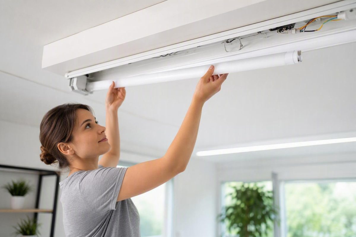
An LED tube can replace a fluorescent tube without changing the housing—but only when the exact LED product is compatible with the fixture’s lamp dimensions, base, ballast or direct-wire arrangement, voltage, lamp holders, controls, and operating conditions. Matching the old lamp’s length or T designation is not enough.
Choosing an LED replacement for a fluorescent fixture therefore starts with an audit, not a product search. Once you know what is inside the fixture and whether the housing is worth retaining, you can compare six practical paths: Type A, Type B, Type AB, Type C, an internal LED retrofit kit, or complete fixture replacement.
This is a planning guide, not a wiring manual. Any work that opens a line-voltage wiring compartment, removes or bypasses a ballast, alters lamp holders, installs a driver, or replaces a fixture should follow the selected product’s instructions and applicable local requirements, with a qualified electrician where appropriate.
Start Here: The Six LED Upgrade Paths
The six paths differ mainly in how much of the fluorescent system remains:
- Type A ballast-compatible tube: The fluorescent lamps are replaced, but a compatible existing ballast remains.
- Type B ballast-bypass tube: The ballast is removed or bypassed, and the LED tube receives line voltage according to its own wiring design.
- Type A+B or AB hybrid tube: The tube can operate from a compatible ballast and may also support direct-wire operation under product-specific conditions.
- Type C external-driver system: The fluorescent ballast is replaced by a separate LED driver that powers compatible lamps or modules.
- Internal LED retrofit kit: The housing remains while the lamps, ballast, and other internal lighting components are replaced.
- Complete LED fixture replacement: The fluorescent fixture is removed and a purpose-built LED fixture takes its place.
These categories describe electrical architectures, not quality rankings. Type A retains a supported fluorescent ballast. Type B removes ballast dependence but requires line-voltage modification. Type AB may support a staged transition. Type C substitutes a dedicated LED driver for the fluorescent ballast. Retrofit kits rebuild more of the lighting system inside the old shell, while complete replacement removes the entire assembly. Commercial guides document the distinctions among Type A, Type B, Type AB, and retrofit kits, while Type C is separately described as an external-driver architecture (Jarvis Lighting; PacLights).
Use this decision sequence:
- Inspect the fixture. Is the housing mechanically sound, securely mounted, and suitable for its location?
- Identify the existing system. Record the complete lamp code, ballast model, fixture voltage, lamp holders, controls, and lamp arrangement.
- Set the installation boundary. Decide whether the work can remain a supported lamp exchange or whether qualified line-voltage modification is acceptable.
- Define the lighting result. Establish the required illumination, distribution, color quality, glare control, dimming, and emergency functions.
- Compare total project cost. Include products, installation, repairs, controls, disposal, energy use, maintenance, access, and downtime.
Physical fit establishes only that a tube may occupy the available space. It does not prove that the ballast can operate it, that the lamp holders support its power-entry design, that the voltage is correct, or that the finished fixture will provide suitable light. No conversion method is universally best.
Audit the Existing Fixture Before Shopping
Complete one worksheet for each distinct fixture type.
| Audit item | What to record | Why it matters |
|---|---|---|
| Fixture identification | Room, fixture number, manufacturer, model | Connects purchasing and maintenance records to the correct fixture |
| Number of lamps | One, two, three, four, or another arrangement | Affects quantity, wiring configuration, output, and cost |
| Complete lamp code | Photograph and transcribe the full marking | Identifies more than nominal length or diameter |
| T designation and diameter | T5, T8, T12, or another format | Narrows the physical lamp family |
| Length and shape | Straight, U-bend, or another shape; actual dimensions | Determines fit, bend spacing, and clearance |
| Base | Bi-pin, R17D, or the exact marked base | Prevents selection by length alone |
| Ballast | Manufacturer, complete model, lamp combinations, input rating | Required for Type A and ballast-mode Type AB compatibility |
| Fixture input voltage | Exact marked voltage or voltage range | Must suit the selected conversion system |
| Lamp holders | Condition, mounting, and shunted or non-shunted status if established | Critical for many direct-wire designs |
| Controls | Switch, dimmer, sensor, daylight control, building system | All connected components must operate together |
| Special systems | Emergency battery equipment or other backup function | May require a specifically compatible solution |
| Location | Dry, damp, cold, hot, dusty, enclosed, impact-prone, food-service | Determines required application and environmental suitability |
| Housing condition | Rust, corrosion, heat damage, wiring, lens, mounting | Helps determine whether retaining the fixture is sensible |
| Lighting target | Existing deficiencies and required illumination | Prevents a compatible but visually poor conversion |
Common linear fluorescent designations refer to nominal tube diameter. T5 is approximately 5/8 inch, T8 approximately 1 inch, and T12 approximately 1.5 inches. Common straight lengths include 2, 4, and 8 feet, but replacement products also exist in 18-inch and 3-foot lengths, U-bend shapes, and multiple base configurations (Super Bright LEDs tube guide).
Record the complete lamp code rather than estimating by sight. Two lamps can share a nominal length and T designation while differing in base, electrical requirements, output, or shape. U-bend replacements must also match bend spacing and available clearance. Base identification becomes especially important with long lamps: one retailer listing, for example, shows an 8-foot T8 direct-wire tube with an R17D base, illustrating why “8-foot T8” is not a complete specification (LightUp replacement-tube listings).
The ballast label is equally important for Type A and ballast-mode Type AB products. Record the manufacturer, full model number, supported lamp combinations, and input rating. If the label is not externally accessible and viewing it requires removal of a wiring-compartment cover, assign that inspection to a qualified person. Internal access should occur only after breaker power has been switched off and absence of voltage has been confirmed with an appropriate tester.
Inspect the complete fixture rather than focusing only on the lamps. Look for:
- Rust or corrosion on the housing and cover
- Heat discoloration or melted components
- Brittle, cracked, or visibly deteriorated wiring
- Cracked, loose, burned, or poorly retained lamp holders
- A broken, yellowed, loose, or insecure diffuser
- Missing covers or exposed components
- Loose mounting or a housing pulling away from the ceiling
- Insufficient room for the selected driver or retrofit components
- Evidence that the fixture is unsuitable for its environment
Record operating conditions that can change product suitability. A garage may be cold, damp, dusty, or exposed to impact. An enclosed fixture may retain heat. Food-service or emergency-lighting applications can impose requirements not addressed by a generic “indoor LED tube” description. The selected lamp, driver, kit, or fixture must be documented as suitable for the actual application.
A matching T-number and nominal length establish neither ballast nor voltage compatibility. They also say nothing about the lamp-holder arrangement, controls, environment, emergency function, or resulting illumination.
Type A, Type B, Type AB, Type C, and Retrofit Kits Compared
Use this table to narrow the options after completing the audit:
| Method | What remains in the fixture | Ballast dependence | Electrical modification | Essential compatibility checks | Future maintenance considerations | Typical reason to consider it |
|---|---|---|---|---|---|---|
| Type A | Housing, lamp holders, wiring, fluorescent ballast | Requires a supported existing ballast | Usually limited to a compatible lamp exchange | Exact ballast model, dimensions, base, controls, voltage, location | Ballast remains in the power path and may fail later | Lowest-disruption option for a sound fixture with a supported ballast |
| Type B | Housing and some existing wiring or lamp holders, depending on design | None after proper bypass or removal | Line-voltage fixture modification | Single- or double-ended design, lamp holders, voltage, instructions, labels, controls | No fluorescent ballast; future relamping must use the correct LED type | Remove ballast dependence while retaining a suitable housing |
| Type AB | Initially similar to Type A; later may be configured like Type B | Required in ballast mode, not in direct-wire mode | None initially if supported; line-voltage work if converted later | Compatibility in the selected mode, ballast model, lamp holders, voltage, instructions | Requires accurate records of each fixture’s current operating mode | Retain a supported ballast now with a documented direct-wire option later |
| Type C | Housing and compatible lamp holders or modules | Uses an external LED driver instead of a fluorescent ballast | Ballast replacement and driver installation | Driver-to-lamp compatibility, input voltage, controls, space, thermal conditions | Driver becomes a separate service component | Obtain a coordinated LED power system while retaining the housing |
| Internal retrofit kit | Primarily the outer housing | Normally uses the kit’s driver | Significant internal rebuild | Kit suitability, housing dimensions, driver, optics, controls, environment | Service depends on compatible drivers, modules, and parts | Improve electrical and optical control without removing the housing |
| Complete fixture | None of the old lighting system | Not applicable | Old fixture removed and new fixture connected | Mounting, supply voltage, controls, environment, distribution, emergency function | Future service follows the new fixture’s design | Replace a damaged, unsuitable, poorly located, or optically inadequate fixture |
Type A: ballast-compatible
A Type A tube operates through an existing fluorescent ballast. The exact ballast model—not merely a broad description such as “electronic T8 ballast”—should appear in the LED manufacturer’s current compatibility information.
Type A is attractive when the fixture is sound, the ballast is serviceable and supported, and minimizing disruption is important. The tradeoff is that the ballast remains part of the system. It continues to draw power and remains a possible failure point; a failed ballast can leave an otherwise functional Type A tube dark.
Retain the compatibility list or dated documentation used for the project. Product revisions can make a vague maintenance note such as “uses plug-and-play LEDs” inadequate for later purchasing.
Type B: ballast bypass
A Type B tube receives line voltage after the fluorescent ballast is removed or bypassed. This eliminates ballast dependence, but it also changes the electrical configuration inside the fixture.
Type B is therefore not simply a different lamp purchase. The installer must verify the lamp’s power-entry design, input voltage, lamp-holder requirements, wiring arrangement, supplied labels, control compatibility, and fixture suitability. Labor for internal modification and any lamp-holder replacement belongs in the project budget.
Type AB: hybrid
A Type AB tube may begin operation through a compatible ballast and later be configured for direct-wire use. That flexibility can support phased work: lamps can be replaced first, with ballast bypass performed later during a planned electrical project or after a ballast failure.
“Hybrid” does not mean universally compatible. Ballast mode still requires an approved ballast. Direct-wire mode still requires the correct voltage, lamp holders, configuration, instructions, and labeling. Maintenance records must identify which mode each fixture currently uses.
Type C: external driver
A Type C system removes the fluorescent ballast and installs a separate LED driver that powers compatible LED lamps or modules.
The driver must fit the housing, suit the input supply and operating environment, support the connected controls, and be paired with approved LED components. Long-term serviceability matters because a future technician may need a compatible driver or module rather than a commodity replacement tube.
Internal retrofit kit
A light-engine, gear-tray, strip, or troffer retrofit kit retains the outer housing but replaces more of the internal lighting system. Depending on the kit, the lamps, ballast, lamp holders, reflector, and other optical parts may all be removed. A new LED module and driver form a coordinated system.
A kit may provide greater control over distribution and glare than tubes installed behind optics designed for fluorescent lamps. That potential does not guarantee that every kit will outperform every tube or complete fixture. Housing suitability, listing documentation, labor, controls, thermal conditions, optics, and replacement-part availability remain product-specific.
The right method depends on fixture condition, documented compatibility, required lighting, controls, installation labor, maintenance strategy, parts availability, and total cost—not a universal ranking.
Type B Details: Single-Ended, Double-Ended, and Lamp Holders
Type B is a category, not a universal wiring format.
In a single-ended design, line and neutral are supplied to separate contacts at one designated end of the lamp. Because those contacts must remain electrically separate, single-ended Type B products commonly require a non-shunted lamp holder at the powered end.
In a double-ended design, power is distributed between opposite ends according to the selected lamp’s architecture. Some double-ended products can use existing shunted or non-shunted lamp holders, but this cannot be generalized to every product or fixture. The manufacturer’s instructions control.
Conceptually, the distinction is:
Type A
Branch circuit → fluorescent ballast → lamp holders → compatible LED tube

Type B
Branch circuit → product-specified lamp-holder arrangement → Type B LED tube
                  (fluorescent ballast removed or bypassed)
A shunted lamp holder electrically joins its two contacts; a non-shunted holder keeps them separate. Identification may require the lamp-holder model and manufacturer documentation or continuity testing with the circuit isolated. Testing inside the wiring compartment belongs with a qualified person.
Some universal tubes can be installed as either Single-End or Dual-End Type B How to Install an LED Tube Light Replacement | Super Bright LEDs. The selected manufacturer’s instructions must govern the power-entry arrangement, lamp-holder requirements, voltage, tube orientation, installation sequence, and modification labels. Commercial guidance on ballast-bypass conversions also warns that installing a fluorescent lamp in a direct-wired fixture can result in immediate failure or another hazard (Regency Supply ballast-bypass guidance).
Clear relamping or modification labeling helps prevent that mistake. The label should communicate the conversion and permitted replacement lamp as directed by the selected product’s instructions. Maintenance records should repeat the information in case the fixture label later becomes damaged, obscured, or unreadable.
Direct-wire conversion involves line voltage and should be assigned to a qualified electrician where required. Existing conductor colors, previous modifications, and fixture arrangements must not be assumed, even when fixtures look identical from below.
Choose the Light, Not Just the Tube
Fluorescent wattage is not a complete LED replacement specification. It describes electrical input, not how much useful light reaches a desk, floor, shelf, wall, or workbench.
Start with the task:
- How much illumination is needed at the work surface?
- Is vertical light important for shelves, faces, equipment, or walls?
- Does the space need broad uniformity or concentrated output?
- Is the current installation too dim, too bright, glary, or uneven?
- Must the lamp operate behind a diffuser or within a deep reflector?
- Are there dark zones that the conversion should correct?
Lamp lumens and delivered light are not the same.
Consider whether the proposed conversion could create striping through a lens, dark bands between tubes, excessive contrast, bright points, glare, or reduced vertical illumination. Tube orientation can matter, especially when the lamp rotates in its holders. For a substantial project, test a representative fixture and evaluate the actual work plane before purchasing in volume.
Visible replacement listings commonly offer choices such as 3500K, 4000K, and 5000K, with broader ranges available elsewhere in the LED market (LightUp replacement-tube listings). Select color temperature according to the space, finishes, visual task, adjacent lighting, and user preference.
CRI is one indication of how faithfully colors may appear under a light source. One commercial planning guide suggests a CRI of at least 80 where color fidelity matters, but that is a general recommendation rather than a universal project standard. Color-critical work may require evaluation beyond the headline CRI value.
Controls require system-level verification. Check the LED lamp or module, ballast or driver, dimmer, occupancy sensor, daylight controller, emergency equipment, and building-control interface together. “Dimmable” on a product description does not establish compatibility with every dimmer or prove that a ballast-mode combination will dim correctly. Retailer listings include both dimmable and non-dimmable LED tubes, so dimming cannot be assumed.
Use this specification checklist when comparing products:
- Lumen output
- Distribution or beam characteristics
- Expected delivered illumination
- Color temperature
- CRI and any additional color-quality information required
- Flicker information and stated test method
- Dimming method and compatible controls
- Input voltage or supported ballast
- Lamp base and physical dimensions
- Single- or double-ended power arrangement where applicable
- Suitability for dry, damp, cold, hot, enclosed, dusty, or impact-prone locations
- Emergency-system compatibility
- Warranty terms and exclusions
- Replacement-part availability
- Safety-listing documentation for the exact model and intended application
- Installation instructions and required labels
Do not treat every logo or qualification shown in a retailer listing as interchangeable. Confirm the exact model through its documentation and the relevant program or certification record rather than assuming that a mark applies to every option in a product family.
When to Retrofit the Housing—and When to Replace It
Retrofitting is a reasonable candidate when the housing is mechanically sound, securely mounted, correctly located, large enough for the specified components, and capable of supporting the intended light distribution and controls.
Retaining a suitable housing may reduce removal work, disruption, ceiling repair, and discarded fixture material. These benefits are project-specific. They can disappear if damaged lamp holders must be replaced, wiring repaired, controls modified, or aging fixtures revisited repeatedly.
Complete replacement becomes the stronger candidate when you find:
- Significant rust or corrosion
- Cracked, loose, or heat-damaged lamp holders
- Brittle or suspect wiring
- Heat damage within the fixture
- A broken or insecure lens
- Poor mounting or structural damage
- A fixture unsuitable for the actual environment
- Insufficient room for approved components
- Optics that cannot provide the required distribution or glare control
- A planned change in layout, ceiling, or lighting purpose
A new fixture may also be preferable when the old housing cannot deliver the required environmental suitability, emergency function, dimming behavior, sensor integration, vertical illumination, or visual comfort. Reusing the shell offers little value if the completed system performs poorly or is difficult to maintain.
A tube retrofit and an internal retrofit kit are not the same. A tube conversion primarily substitutes lamps and may retain the ballast or existing lamp holders. A kit rebuilds more of the internal system, generally introducing a dedicated LED driver and light engine and sometimes changing the optical components.
Consider three common scenarios:
- Sound four-foot T8 strip fixture with a supported ballast: Type A may be a low-disruption candidate if the light distribution, controls, and environment are suitable.
- Aging but serviceable housing: Type B, Type C, or an internal kit may remove dependence on the old ballast, but labor, lamp-holder condition, optics, and documentation must be considered.
- Corroded or poorly located fixture: Complete replacement is the stronger candidate because retaining the shell preserves its mechanical or layout deficiencies.
T12 fixtures do not have one mandatory conversion path. Depending on the lamp, ballast, lamp holders, housing, and project requirements, options may include supported plug-and-play lamps, ballast bypass, remote-driver systems, internal kits, or complete replacement. A supplier’s overview illustrates this range, but compatibility still has to be established for the exact installation (Regency Supply T12 conversion overview).
The decision should weigh fixture condition, electrical architecture, lighting outcome, controls, labor, serviceability, downtime, and total cost. Comparing only the price of one LED tube with one new fixture omits most of the project.
Plan a Safe, Documented Conversion
A supported Type A lamp exchange and an internal fixture modification are fundamentally different scopes.
A Type A project may be limited to replacing lamps in a sound fixture after breaker power is switched off, provided the existing ballast is approved for the exact LED product. Opening a wiring compartment, removing or bypassing a ballast, altering lamp holders, installing a driver, fitting a retrofit kit, or replacing the fixture goes beyond a basic lamp exchange.
Before wiring or internal electrical components are touched, switch off power at the circuit breaker and confirm absence of voltage with an appropriate tester. Ballast bypass, external-driver installation, retrofit-kit installation, and complete fixture replacement can involve line voltage and should be performed by a qualified person in accordance with the exact product instructions and applicable local requirements (Root Electric safety guidance).
Do not rely on universal conductor-color instructions. Existing wiring may have been repaired, extended, repurposed, or modified, and practices can vary. The actual circuit and fixture arrangement must be identified rather than inferred.
Before work begins, verify and retain:
- Exact product manufacturer and model
- Safety-listing documentation for the model and intended application
- Current installation manual
- Current ballast compatibility list for Type A or ballast-mode Type AB
- Required lamp-holder type
- Input-voltage rating
- Single- or double-ended power arrangement
- Fixture-size and environmental limitations
- Dimming and control requirements
- Emergency-system compatibility
- Required modification or relamping labels
- Warranty conditions affected by installation or fixture modification
No universal answer applies to every product or jurisdiction. Resolve these matters with the product manufacturer, qualified installer, inspection authority, or other relevant local party before purchase when they could affect approval.
This publication treats line-voltage work as outside the scope of routine DIY lighting advice; its stated electrical-work boundary assigns panel work to an electrician (LED Lighting Zone terms). Ballast bypass should likewise not be presented as an ordinary lamp swap.
Document the completed installation. A useful maintenance record includes:
- Fixture location or asset number
- LED manufacturer and complete model
- Conversion type
- Ballast model retained, if any
- Driver model, if installed
- Documented direct-wire configuration
- Lamp-holder type or replacements
- Installation date
- Installer or contractor
- Applied labels
- Control settings
- Warranty information
- Photographs of labels and the completed internal arrangement, where appropriate
After installation, confirm:
- Stable illumination
- Expected output and acceptable uniformity
- No unusual noise, odor, heat, or visible flicker
- Correct operation of dimmers, sensors, and daylight controls
- Correct emergency operation where applicable
- Secure lamps, modules, covers, and lenses
- Required warning and relamping labels in place
- Updated maintenance and warranty records
This article intentionally does not provide a conductor-by-conductor wiring schematic. The selected manufacturer’s instructions, actual fixture configuration, applicable local requirements, and qualified professional judgment must govern the work.
Troubleshoot an LED Tube That Does Not Work
Switch off breaker power before reseating a lamp or inspecting fixture components. Diagnosis inside a wiring compartment belongs with a qualified person; do not experiment with lamp holders or conductors while the fixture is energized.
For a Type A tube that remains dark, check the least invasive possibilities first:
- Confirm that the circuit, switch, and relevant control are on.
- Isolate power and verify that the tube is fully seated.
- Check orientation if the product specifies one.
- Compare the exact ballast model with the manufacturer’s current compatibility list.
- Inspect externally visible lamp-holder condition without disturbing wiring.
- Confirm that the tube matches the required dimensions and operating conditions.
A tube can fit perfectly and still fail because the ballast cannot start or operate that LED product. If the previous fluorescent lamp worked, that proves only that the ballast operated that fluorescent lamp—not that it supports a particular Type A LED tube.
For Type B, Type AB in direct-wire mode, Type C, or an internal kit, compare the installed model and documented configuration with the manufacturer’s instructions. Do not attempt generic rewiring corrections from a diagram intended for another product.
Controls form a separate troubleshooting category.
For flicker, noise, intermittent operation, or uneven output, organize the diagnosis into categories:
- Lamp-to-ballast compatibility
- Driver or retained-ballast condition
- Loose, cracked, or damaged lamp holders
- Incorrect product configuration
- Incompatible controls
- Unsuitable supply voltage
- Emergency-equipment interaction
- Product failure
- Excessive heat or an unsuitable enclosure
If the system illuminates but performs poorly, reassess the lighting design. Check tube orientation, diffuser and reflector interaction, lamp output, distribution, glare, dark bands, vertical illumination, and actual light at the work surface. A functioning LED is not necessarily a successful replacement.
Stop using the fixture and obtain qualified evaluation if you observe heat damage, a burning odor, arcing, damaged lamp holders, exposed conductors, repeated breaker operation, or uncertainty about an earlier modification. Those conditions require fault diagnosis rather than further lamp swapping.
The compact troubleshooting flow is:
Identify the conversion type → isolate power → verify the exact product and documented configuration → check ballast, driver, lamp-holder, and control compatibility → assess fixture condition and lighting performance → escalate unsafe or unresolved faults.
Compare Total Cost and Dispose of Fluorescent Lamps Responsibly
Do not base the decision on a generalized savings percentage or payback claim. Build the comparison from the actual installation.
Initial project-cost worksheet
| Cost input | Type A | Type B | Type AB | Type C or kit | Complete fixture |
|---|---|---|---|---|---|
| Lamps, modules, kits, or fixtures | |||||
| Quantity | |||||
| Electrician or installer labor | |||||
| Lamp-holder replacement | |||||
| Fixture repair | |||||
| New controls or control adaptation | |||||
| Emergency-system work | |||||
| Mounting or ceiling repair | |||||
| Permits or inspection, if applicable | |||||
| Fluorescent-lamp disposal | |||||
| Ballast or component disposal | |||||
| Downtime or access equipment | |||||
| Verified rebate | |||||
| Net initial cost |
For operating cost, use documented or measured system wattage rather than lamp wattage alone. Include ballast draw retained by a Type A installation.
Annual energy use (kWh) =
system watts × annual operating hours ÷ 1,000

Annual electricity cost =
annual energy use × local electricity rate
Apply the same operating schedule and electricity rate to each option unless a genuine controls change will alter operating hours. If controls are included, show those assumptions separately rather than hiding them inside a broad savings percentage.
Maintenance deserves its own comparison:
- Will Type A require future ballast replacement?
- Can lamps, drivers, or modules be accessed without special equipment?
- Are replacement parts likely to remain available?
- Does the warranty cover labor or only the component?
- Must a failed integrated fixture be replaced as a whole?
- Does a kit use a serviceable driver?
- What does a repeat visit to a high ceiling or occupied area cost?
- Could maintenance personnel install the wrong lamp in a modified fixture?
- Is the conversion clearly labeled and documented?
Count a rebate only after checking the exact model against the current local program. Efficiency qualification is not a safety listing, and neither automatically proves compatibility with the existing fixture.
Do not assume a fixed savings percentage, service life, or payback period. Results depend on the existing fluorescent system, selected LED product, ballast losses, controls, labor, operating hours, electricity price, maintenance access, and environmental conditions.
Fluorescent lamps contain mercury. Keep removed lamps intact, protect them from breakage during temporary storage and transport, and take them to an appropriate local lamp-recycling or hazardous-waste program rather than placing them casually in ordinary waste. Follow the receiving program’s packaging instructions (Root Electric disposal guidance).
Confirm the requirements with the relevant local waste or recycling program rather than applying one rule to every component.
The final purchasing test is straightforward. The selected solution should be:
- Electrically and mechanically compatible
- Suitable for the actual location
- Capable of producing the required light
- Compatible with controls and emergency functions
- Supported by clear product documentation
- Safe and practical to install
- Serviceable after installation
- Economical under realistic project assumptions
The best LED replacement is determined by the existing fixture, not tube length alone. Finish with a completed fixture audit, a confirmed conversion type, documented product compatibility, a lighting-performance target, and a realistic total-cost comparison. A supported Type A tube may suit a sound fixture with a compatible ballast. Type B, Type C, and retrofit kits involve deeper modification. A damaged, corroded, poorly located, or optically unsuitable fixture may justify complete replacement.
Can I replace a fluorescent tube with an LED tube without removing the ballast?
Yes, if you select a Type A or suitable Type AB tube and the exact existing ballast model appears in the LED manufacturer’s current compatibility information. The tube must also match the required dimensions, base, controls, operating environment, and other stated conditions.
Do not assume that every “plug-and-play” tube works with every ballast. If the ballast is unsupported, damaged, or unsuitable for continued service, compare another documented conversion path.
What is the difference between Type A, Type B, Type AB, and Type C LED tubes?
Type A operates through a compatible fluorescent ballast. Type B removes or bypasses the ballast and receives line voltage according to the lamp’s specific power-entry design. Type AB can support ballast operation and direct-wire operation under the conditions stated for that product. Type C replaces the fluorescent ballast with a separate LED driver that powers compatible lamps or modules.
These categories do not indicate which option is best. They describe how the system is powered and how much installation work is required.
How do I know whether my fluorescent fixture has shunted or non-shunted lamp holders?
A shunted lamp holder joins its two contacts electrically; a non-shunted holder keeps them separate. The configuration may be established from the lamp-holder model and manufacturer documentation or through continuity testing with power isolated.
Do not rely solely on appearance. Fixture wiring can affect the arrangement, and opening or testing the wiring compartment should be assigned to a qualified person. The selected LED tube’s instructions must state which lamp-holder configuration it supports.
Is it better to retrofit a fluorescent fixture or replace the complete fixture?
Retrofit is a good candidate when the housing is sound, securely mounted, suitably located, large enough for the specified components, and capable of producing the required light. It may reduce removal work and disruption.
Complete replacement is generally more attractive when the fixture is corroded, heat-damaged, poorly mounted, optically inadequate, incompatible with required controls, or unsuitable for its environment. It also makes sense when the lighting layout or intended use is changing. Compare the completed systems, not just lamp and fixture prices.
What should I do with old fluorescent tubes after an LED conversion?
Keep fluorescent lamps intact, protect them from breakage, and take them to an appropriate local lamp-recycling or hazardous-waste program because they contain mercury. Ask the receiving program how the lamps should be packaged and transported.
Do not assume that removed ballasts, drivers, or emergency batteries follow the same disposal route. Check the applicable local requirements for each component, especially for older equipment.