
How to Choose Kitchen LED Strips
Even a correctly sized driver cannot fix a connector-width mismatch, incompatible dimmer or strip that will not fit the selected channel.
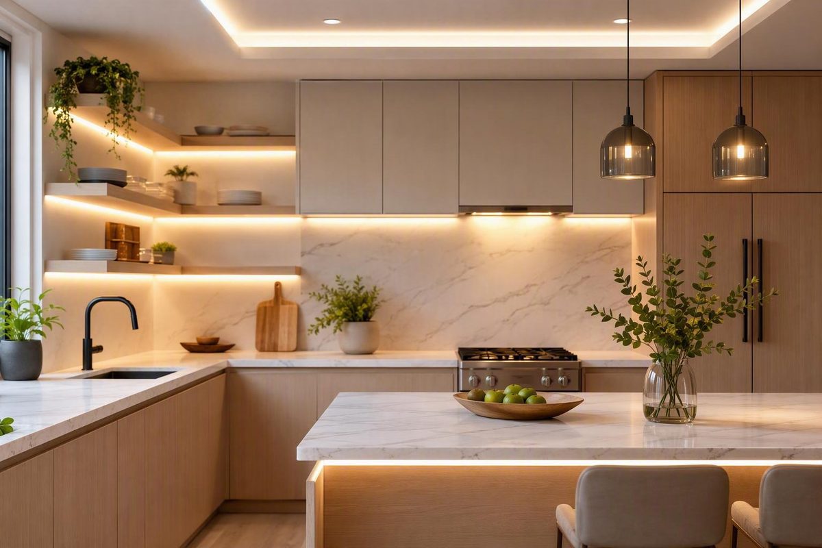
Strip LED lighting for kitchens works best when it is designed as a complete system, not purchased as a reel of tape plus an arbitrary power supply. The strip, driver, wiring, controls, connectors, channels, placement, and cabinet layout all affect the result.
Start with the countertop task. Map the cabinets, choose the required output and white tone, select a strip format and voltage suited to the layout, calculate the electrical load, and test the complete system before permanent mounting. This process reduces the risk of uneven brightness, visible LED dots, shadow lines, incompatible dimming, failed connections, and inaccessible power equipment.
This is a product-planning guide rather than a substitute for an electrical design, product instructions, or local code advice. Wire selection, concealed wiring methods, equipment listings, sink and range locations, and household-voltage work must be resolved using the documentation for the exact products and the requirements that apply where the system will be installed.
Start With the Kitchen Task, Layout, and Type of Light
They may use similar products, but they do not necessarily need the same output, placement, or optics as countertop task lighting.
Define each run as task, accent, or both before choosing a strip. A low-output strip that creates an attractive backsplash glow may be disappointing over a dark worktop. Conversely, a high-output task strip can look harsh when exposed above cabinets or reflected from a polished surface.
Map the kitchen before shopping
Draw a plan showing:
- Every cabinet section that will be illuminated
- The usable mounting length under each cabinet
- Gaps caused by windows, ranges, sinks, refrigerators, and open shelving
- Inside and outside corners
- Cabinet lips, face frames, dividers, and trim
- Existing outlets and switches
- Desired control locations
- Possible driver or power-supply locations
- Routes for low-voltage wire between cabinet banks
- Sections intended for task lighting, accent lighting, or both
Do not treat total cabinet width as one uninterrupted strip run. A kitchen with several separated cabinet banks requires individual measurements, gap-bridging wire, connectors, and a deliberate power-feed arrangement. The geometry affects cut intervals, current, voltage drop, and whether one driver or several supplies make sense.
Also decide whether the system will be plug-in or hardwired. A plug-in system can simplify the household-voltage side when a suitable accessible outlet already exists. Hardwiring may provide a cleaner appearance, but the driver, switching method, line-voltage connections, and access arrangements must all be suitable for that installation.
Compare the principal lighting formats
Field-cuttable flexible tape provides the most exact fitting. It can accommodate irregular cabinet dimensions, but only when cut at the product’s designated marks. Every separate section then needs compatible connectors or soldered leads, plus wire to cross corners and cabinet gaps.
Fixed-length linkable strips reduce cutting and assembly work. They may arrive with coordinated linking cables, controls, and a power supply, but exact fitting is limited by the available module lengths. One documented Armacost system uses non-cuttable 10-, 22-, and 34-inch sections and permits up to eight linked strips, so the cabinet layout must suit those modules rather than being trimmed precisely on site (Armacost product specifications).
Rigid light bars are finished fixtures rather than flexible tape. They may simplify mounting and connections, but their length must fit within the usable cabinet width. Keep bar sizing separate from tape-light sizing: bars differ in cuttability, optics, linking methods, wiring, and mounting hardware.
Conventional flexible tape uses visibly spaced LEDs. Whether it appears smooth depends on LED density, concealment, channel depth, diffuser material, brightness, and viewing angle.
COB-style tape places light-emitting elements closely enough to create a more continuous-looking line. It can help where reflections or sightlines reveal conventional LED dots, but it still needs to be evaluated for output, power consumption, cut interval, channel fit, operating conditions, and connector availability.
Static-white tape produces one white color temperature. It is generally the simplest option when the desired white tone is already known.
Tunable-white tape changes between warmer and cooler whites.
For useful white task lighting, prioritize dedicated-white, tunable-white, or RGBW products. RGB-only tape creates nominal white by combining its red, green, and blue channels.
Use this pre-shopping worksheet
| Planning item | Measurement or decision |
|---|---|
| Total illuminated length | |
| Length of each separate section | |
| Distance across each gap | |
| Number and type of corners | |
| Task, accent, or combined purpose | |
| Countertop depth and finish | |
| Desired control locations | |
| Available outlets or power access | |
| Candidate driver location | |
| Plug-in or hardwired preference | |
| Static white, tunable white, or color | |
| Need for channels or angled profiles | |
| Visible sightlines from seating areas |
This worksheet is more useful than beginning with a preferred reel length. It turns the project into defined sections, loads, connections, and optical goals.
Choose Brightness, White Tone, and Color Quality
Choose brightness for the countertop rather than relying on labels such as standard, bright, or high output. Compare documented lumens per foot, and record watts per foot separately for driver sizing.
Seller guidance places kitchen under-cabinet lighting at roughly 200–500 lumens per foot, but this is a commercial planning range rather than an independent lighting standard. The lower end can be a starting point for shallow, pale, or reflective counters with useful ambient light. The upper end may be more appropriate for deeper or darker work areas. Flexfire, for example, lists kitchen strip options near 250 and 500 lumens per foot (Flexfire kitchen strip options).
A pale polished countertop may reflect a moderate-output strip strongly, while a dark matte surface may make the same strip appear weak. Counter depth, cabinet height, channel angle, diffuser loss, backsplash reflectivity, and existing ceiling lights also affect the result.
When uncertain, selecting enough output for the task and adding a verified compatible dimming system usually provides more flexibility than installing a strip that is underpowered at full output. That does not mean buying the most powerful strip available: unnecessary output increases connected load and can increase glare and thermal demands.
Choose color temperature in context
Color temperature describes the apparent warmth or coolness of white light:
- Approximately 2700K–3000K: warmer or more golden
- Approximately 3500K–4000K: more neutral in appearance
- 5000K and above: cooler or more daylight-like
These are appearance categories, not rankings of task performance. Flexfire uses similar warm, neutral, and cool groupings in its kitchen product range, while individual products may offer different selectable steps.
Compare the under-cabinet light with ceiling fixtures and pendants before ordering the entire system. Two products both marketed as “warm white” can still look different. A mixture of warm pendants, neutral strips, and cool ceiling fixtures may make the room feel visually disconnected unless that layering is intentional.
Exact matching is not mandatory. Neutral countertop lighting with warmer decorative pendants can work well when the contrast is deliberate. If the preferred appearance changes between daytime work and evening ambience, tunable-white tape offers more flexibility than one fixed color temperature.
Look beyond color temperature
Check whether the manufacturer publishes:
- A color-rendering index, or CRI
- Additional color-rendering information
- Color-temperature tolerance or binning data
- Consistency specifications across reels or modules
- Dimming behavior and minimum dimming level
- Flicker information, if available
Published color-rendering data can help compare how products reproduce food, wood, stone, tile, and painted surfaces. The available evidence does not establish a universal minimum CRI or R9 requirement, so do not treat an unsupported threshold as mandatory.
Buy adjacent visible sections with matching specifications and, where practical, from the same product family. Power the modules or reels together before installation. A small color difference that seems unimportant on a workbench may become conspicuous when separate cabinet sections illuminate one continuous backsplash.
Finally, voltage does not determine brightness. A 24V strip is not inherently brighter than a 12V strip. Output depends on lumens per foot, watts per foot, LED density, optical design, diffuser losses, operating conditions, and product quality.
12V or 24V: Match the Voltage to the Run
Neither 12V nor 24V is universally best for kitchen strip lighting.
Use this practical decision rule:
- Consider 12V for short, intricate cabinet sections when the specific product offers useful, finer cutting increments.
- Consider 24V for longer or higher-output runs where lower current can help limit resistance-related voltage loss.
The cutting advantage is product-specific. In one manufacturer comparison, the cited 12V strip has 1-inch cut intervals while its 24V counterpart has 2-inch intervals. The same comparison illustrates a 48-watt load drawing 4 amps at 12V and 2 amps at 24V (Waveform Lighting’s voltage comparison).
The underlying relationship is:
Current = Power ÷ Voltage
At equal power, doubling the voltage from 12V to 24V halves the current. Lower current can reduce voltage lost through strip traces and connecting wire, which is why 24V is often advantageous for longer cabinet runs.
Treat published run lengths as product examples
Some vendor guides cite approximate runs of 5 meters for 12V and 7–10 meters for 24V. These are not universal limits. Super Bright LEDs, for example, gives typical examples of about 16.4 feet for 12V and 32.8 feet for 24V before voltage-drop concerns become significant, while recommending multiple circuits for longer layouts (Super Bright LEDs’ run-length examples).
Actual run length depends on:
- Watts per foot
- Copper-trace resistance in the strip
- Connecting-wire length and resistance
- Conductor size
- Connector resistance
- Whether power enters at one end, both ends, or intermediate points
- Whether cabinet sections are daisy-chained or connected as parallel branches
- The amount of brightness variation considered acceptable
Use the exact strip’s datasheet for cut intervals, maximum connected length, and permitted feed arrangements. Products sharing the same voltage do not necessarily support the same run length.
Recognize and address voltage drop
Possible signs include:
- The far end appears dimmer than the feed end
- Separate cabinet sections differ in brightness
- White or multicolor products change color along a long run
- A section works correctly near the driver but poorly at its far end
Depending on the product documentation and calculated load, possible remedies include:
- Dividing the layout into shorter parallel branches
- Feeding the strip from both ends where permitted
- Adding properly designed intermediate feed points
- Recalculating conductor size for current, distance, and acceptable loss
- Using separate circuits or supplies for distant cabinet banks
- Selecting a suitable 24V product while the system is still being designed
Do not address voltage drop by connecting a higher-voltage supply to a lower-voltage strip. The strip, driver, dimmer, controller, and powered accessories must have compatible voltage ratings. Vendor guidance warns that a 12V strip connected to a 24V supply can overheat or fail, while a 24V strip supplied with 12V may remain off or appear dim (Inspired LED’s voltage-compatibility guide).
Size the Driver and Verify Every Component
A complete under-cabinet system may include:
- LED strip or fixed lighting sections
- A matching-voltage driver or power supply
- Low-voltage wire
- Tape-to-wire and tape-to-tape connectors, or soldered joints
- A wall dimmer, low-voltage dimmer, or controller
- Switch or smart-control hardware
- Aluminum channels and diffusers
- Clips or mounting hardware
- Gap-bridging leads
- Cable-management components
- Suitable terminations and enclosures
These parts must work together electrically and physically. A correctly sized driver does not solve a connector-width mismatch, an incompatible dimmer, or a strip that will not fit inside the selected channel.
Calculate the connected load
Start with:
Installed length × watts per foot = connected load
For example:
10 ft × 3 W/ft = 30 W
Some vendor guidance adds approximately 20% to the calculated load:
30 W × 1.20 = 36 W
That produces a minimum calculated rating of 36 watts under an “add 20%” convention. It is not identical to a rule limiting the connected load to 80% of driver capacity. Under an 80%-loading rule:
30 W ÷ 0.80 = 37.5 W
Use the convention required by the exact driver documentation; do not treat the two calculations as interchangeable. Inspired LED is one vendor that uses a 20% capacity buffer, but manufacturer loading limits, minimum-load requirements, dimming range, temperature limits, and ventilation instructions control for the selected equipment.
As a documented comparison, one installation used about 28 feet of 12V strip rated at 2.9 watts per foot. Its calculated load was approximately 81 watts, and it was paired with a 100-watt supply (Flexfire’s installation example).
When several strips share a supply, their required voltage remains the same, but their wattage and current demands add together. Separate cabinet banks should share a driver only when total load, current, controller capacity, wire distances, feed arrangement, and voltage-drop limits remain within the relevant specifications. Distant banks separated by a range, window, or doorway may be easier to wire and service with separate supplies.
Use a compatibility checklist
| Item | What must match or remain within specification |
|---|---|
| Strip voltage | Driver output and powered controls |
| Total wattage | Driver and controller capacity |
| Total current | Driver, controller, wire, and connector ratings |
| Strip width | Connector and channel dimensions |
| Copper pads | Connector pin count and layout |
| White or color type | Controller channel count and protocol |
| Dimming method | Driver and control architecture |
| Wall dimmer | Named compatibility and permitted load range |
| Wire | Current, distance, routing, and installation location |
| Channels | Strip width, connector clearance, and diffuser fit |
| Environment | Strip, connections, driver, and terminations |
| Run length | Product datasheet and feed design |
A generic “dimmable” label is not enough. One fixed-length Armacost cabinet system explicitly excludes Lutron dimmers, illustrating why named compatibility matters more than assumptions based on a brand name or a dimmable label (Armacost dimmer notice).
Distinguish the two common dimming architectures
With line-voltage wall dimming, a compatible household-voltage dimmer controls a compatible dimmable driver. The driver then supplies low-voltage power to the strip. The dimmer type, driver type, allowed load range, and wiring requirements must agree.
With low-voltage controller-based dimming, the power supply feeds a controller, and the controller varies the output delivered to the strip. This arrangement is common with tunable-white, RGBW, remote, and app-controlled systems.
Do not stack unrelated dimming methods unless the product documentation explicitly permits it.
Choose a concealed driver location that remains accessible for inspection or replacement. Follow the driver’s documented mounting, enclosure, clearance, and ventilation requirements rather than applying one universal clearance rule.
Place the Strip for Even Countertop Light
Placement determines both where the light lands and whether the strip becomes an unwanted visual feature.
Mounting nearer the cabinet front generally sends more light toward the main countertop work area. Moving the strip rearward tends to emphasize the backsplash. Neither position is universally correct because cabinet lips, counter depth, channel angle, reflective surfaces, and normal viewing positions vary.
A front rail may block light from a strip mounted too far forward or too high. In one documented kitchen, shifting the channel about one inch behind the cabinet’s front edge removed a shadow caused by the cabinet lip. That was a solution for that specific kitchen, not a universal setback dimension (documented cabinet-lighting installation).
Test placement before permanent mounting
Temporarily power the strip and hold or tape it in several candidate positions. If practical, test it in both daytime and nighttime conditions. Check:
- Coverage at the front and rear of the counter
- Shadows created by the cabinet lip
- Glare reflected from polished stone or tile
- Bright hotspots on the backsplash
- Visibility of individual LED points
- Visibility of the strip or channel from seated positions
- Consistency between adjacent cabinet sections
- The effect of standing and seated sightlines
- Whether open cabinet doors alter glare
- Whether connectors and wire exits fit in the proposed location
Complete this test before drilling holes, cutting recessed channels, trimming every profile to final length, or exposing permanent adhesive.
Decide whether to use channels and diffusers
An aluminum channel can:
- Keep flexible tape straight
- Provide a repeatable mounting surface
- Hold a removable diffuser
- Protect the tape from casual contact
- Conceal the strip from common sightlines
- Transfer heat away from the strip
A diffuser can soften individual LED points, but it cannot guarantee a perfectly continuous line. The result depends on LED spacing, channel depth, diffuser material, output, viewing angle, and the distance to reflective surfaces.
Higher-density conventional tape and COB-style products can improve visual continuity. Greater density can also increase power demand and heat, depending on the product, so compare watts per foot and channel requirements rather than choosing by LED count alone.
Leave space at channel ends for connector clips, solder joints, cable bends, and wire exits. A strip cut to the channel’s exact internal length may be too long once the connector is attached.
Clean and dry the mounting surface and follow the strip or channel manufacturer’s mounting method. Where the product permits it, channels, clips, screws, or approved supplemental supports may provide a more secure mounting arrangement.
Plan for Sinks, Steam, Grease, and Heat
A kitchen is not uniformly wet or dry. A strip far from the sink may face dust and grease film, while another run may encounter direct splashes or frequent wet cleaning. Lighting near a range may be exposed to steam, airborne grease, and cooking heat.
Do not assume that a product marketed for kitchens tolerates water. The fixed-length Armacost system discussed earlier is specified as IP20 and dry-rated. That product example demonstrates why suitability must be checked rather than inferred from the application name.
One source describes IP20 or IP30 tape as unprotected and IP65 tape as a silicone-coated construction intended for occasional splashes or high humidity. Those descriptions concern strip construction; they do not establish legal or practical suitability for a specific sink, range, or cabinet location (The Hook Up’s discussion of strip construction).
An IP rating addresses enclosure protection under defined conditions. It does not prove that the complete installation is suitable or compliant. The driver, connectors, wire, terminations, channels, and household-voltage connections must also be appropriate for the actual environment.
Cuts, connectors, and cable exits can interrupt the protective construction of a coated or sleeved strip. Use the exact manufacturer’s approved cutting, termination, and sealing instructions rather than assuming the uncut strip’s rating automatically applies to every field-made joint.
Protective construction may also reduce heat dissipation. Follow the strip’s temperature and mounting requirements, and use a compatible channel when the product documentation calls for one.
A cautious kitchen plan should:
- Keep drivers and connections away from direct splash and heavy grease unless documented for that exposure
- Avoid placing strips in unusually hot cooking locations without product approval
- Preserve access to drivers and connectors
- Select components appropriate for expected cleaning
- Evaluate the complete assembly, not only the strip’s IP label
- Verify current product listings, installation instructions, and location requirements
- Refer uncertain sink, range, concealed-wiring, or household-voltage questions to a qualified local professional
For additional background—not as a substitute for product documentation or local requirements—see this guide to water-resistant LED strip IP ratings.
Install in a Test-First Sequence
A test-first installation sequence limits how much work must be undone if a component is incompatible or a connection fails.
- Map the complete layout. Mark every lit section, gap, corner, feed point, control, and driver location.
- Verify component compatibility. Check voltage, wattage, current, strip width, pad layout, connector pin count, control method, and channel dimensions.
- Locate power and controls. Identify the outlets, switches, or household-voltage connections involved.
- Measure each cabinet separately. Allow for face frames, lips, dividers, connector bodies, and wire exits.
- Dry-fit channels and wiring. Confirm that doors, shelves, and trim do not interfere.
- Bench-test the complete system. Test the driver, controller, dimmer, strip, and representative connectors before cutting.
- Cut only at designated marks. Cut spacing is specific to the product.
- Connect one cabinet section. Follow the strip’s marked positive and negative polarity.
- Retest the first section. Check brightness, white tone, dimming, and connection stability.
- Repeat the proven method. Assemble the remaining sections only after the first works correctly.
- Mount the channels or strips. Prepare the surface and use the approved mounting method.
- Route and secure wiring. Keep it protected, organized, and accessible where required.
- Complete a final operational test. Check every section at full output and throughout the intended dimming or tunable-white range.
Common tools and materials include a drill, scissors, wire cutters, wire strippers, appropriately selected low-voltage wire, compatible solderless connectors or soldering equipment, aluminum channels, diffusers, mounting hardware, and cable-management materials.
Follow the positive and negative markings on the strip rather than assuming wire color proves polarity. Accessories and extension leads do not always use identical color conventions.
Low-voltage wire can bridge corners and gaps without forcing flexible tape around a tight bend. Its conductor size and type must be chosen from current, distance, route, voltage-drop design, and installation conditions. If wiring enters a wall, use cable documented as suitable for that application; aspectLED’s installation guidance specifically calls for in-wall-rated wiring when routed through walls (aspectLED’s planning guidance).
Do not automatically daisy-chain every cabinet section. Follow the strip’s maximum run and the controller’s current limit. A long layout may require parallel branches, feeds at more than one point, or separate power supplies.
Keep serviceable components accessible rather than permanently sealing them behind finished surfaces. Concealed does not have to mean inaccessible: a reachable upper-cabinet location or removable panel may preserve both appearance and service access when permitted by the equipment instructions.
Finally, distinguish low-voltage strip assembly from household AC work. Mounting channels and connecting a documented plug-in low-voltage system is not the same as adding an outlet, hardwiring a driver, installing concealed line-voltage cable, or working at an electrical panel. Local law, permitting rules, product instructions, and project scope determine who may perform that work. LED Lighting Zone’s own safety notice states that its coverage concerns low-voltage systems and advises leaving panel work to an electrician (electrical-work boundary). Use a qualified electrician whenever the local requirements or the work involved call for one.
Use a Final Buying and Troubleshooting Checklist
Before ordering, verify the complete bill of materials rather than purchasing the strip first and improvising the rest of the system.
Final buying checklist
- Measured illuminated length, with only the necessary allowance
- Length of each separate cabinet section
- Lumens per foot
- Watts per foot
- White color temperature or tunable range
- Published color-rendering information
- Strip voltage
- Cut interval
- Product-specific maximum-run guidance
- Strip width
- Number and arrangement of copper pads
- Channel internal dimensions
- Clearance for connectors and wire exits
- Driver output voltage
- Driver wattage and current capacity
- Required loading reserve or maximum loading percentage
- Minimum-load and ventilation requirements
- Dimming architecture
- Named wall-dimmer or controller compatibility
- Connector width and pin count
- Wire documented as suitable for the calculated load and route
- Environmental rating
- Relevant product documentation and certifications
- Mounting clips, screws, or approved adhesive support
- Warranty and replacement terms
Confirm that every connector matches both the strip width and the number and arrangement of its pads. A connector intended for static-white tape will not necessarily fit a tunable-white or multichannel strip of the same width.
Power all visible reels or modules together before mounting. Compare brightness, white tone, dimming, and every tunable or color channel. Do not wait until the tape has been cut and adhered to discover that adjacent sections look different.
If a section is completely dark
Check, in order:
- Whether the supply has input power
- Whether its output voltage matches the strip
- Whether the controller is receiving and passing power
- Positive and negative polarity
- Whether the strip was cut at the correct mark
- Connector alignment with the copper pads
- Whether a clip is fully closed
- Whether the section works with a known-good compatible lead
Do not bypass required controls, enclosures, or protective components while testing.
If the far end is dim
Check:
- Total run length
- Watts per foot and connected load
- Connecting-wire length and resistance
- Conductor selection
- Feed location
- Connector condition
- Whether several sections are daisy-chained
- Whether the product permits another feed or power from both ends
The remedy may be a shorter branch, an additional permitted feed, or a separate circuit. A higher-wattage driver alone does not remove resistance from a long strip or connecting wire.
If the lights flicker or dim poorly
Check driver and dimmer compatibility, controller architecture, minimum-load requirements, loose connections, and excessive load. Confirm whether dimming is intended to occur on the line-voltage side of a compatible driver or through a low-voltage controller. Do not assume that the strip itself is defective.
If LED dots or glare are visible
Test one cabinet before changing the entire installation. Possible adjustments include:
- Moving the strip out of the direct sightline
- Changing its distance from the front lip
- Using an angled channel
- Increasing concealment
- Trying a deeper compatible channel
- Testing a different diffuser
- Selecting higher-density or COB-style tape
- Reducing output with a compatible dimmer
If the strip sags or the adhesive fails
Clean contamination from the surface and verify that the substrate is compatible with the approved mounting method. Use compatible channels, clips, or other documented supports where needed. Repeatedly pressing tape onto a greasy or unsuitable cabinet surface is not a dependable correction.
If the system becomes unusually hot
Turn the system off if there is damaged insulation, discoloration, melting, or evidence of an incorrect supply. Check strip wattage, driver loading, ventilation requirements, channel use, protective coatings, connector condition, and proximity to cooking heat. Have the installation evaluated before reuse when the cause is uncertain.
Prices, inventory, warranties, run limits, and compatibility claims can change. Verify every final specification in the current datasheet and installation documentation for the exact strip, driver, controller, connector, and accessory being purchased.
Frequently Asked Questions
How many lumens per foot should kitchen under-cabinet LED strips provide?
Roughly 200–500 lumens per foot is a seller-derived planning range, not a universal requirement. The lower end may suit shallow, pale, or reflective counters with useful ambient illumination. Darker or deeper work areas may justify considering the upper end (Flexfire’s listed kitchen output options).
Placement, countertop reflectivity, diffuser loss, and existing light can substantially change the result. When possible, test a sample. Choose enough output for the task and use a verified compatible dimmer for flexibility rather than relying on an underpowered strip that cannot be made brighter.
Is 12V or 24V better for kitchen LED strip lighting?
Use the voltage that best fits the selected product and cabinet layout. A 12V strip can be useful for short sections when it offers finer cut intervals. A 24V system is often advantageous for longer or higher-output runs because it draws half the current of a 12V system at equal power, helping limit resistance-related voltage loss (Waveform Lighting’s 12V and 24V comparison).
Neither voltage guarantees a particular brightness or run length. Check the exact product’s watts per foot, cut interval, run guidance, and approved feed arrangements. All powered components must have compatible voltage ratings.
Can one driver power LED strips on several separate cabinet sections?
Yes, provided that all sections require the same voltage and their combined wattage and current remain within the driver, controller, connectors, wiring, and product-specific loading limits.
Wire distance and feed arrangement still matter. A centrally located driver with parallel branches may work well, but distant cabinet banks can be easier to wire and troubleshoot with separate supplies. Sufficient driver wattage alone does not prove that controller capacity or voltage drop is acceptable.
Do I need aluminum channels and diffusers under kitchen cabinets?
Not in every installation, but they are often useful. Channels can keep tape straight, hold a diffuser, protect the strip from casual contact, provide a consistent mounting surface, and transfer heat away from the tape.
Diffusers do not guarantee a dot-free line. LED spacing, channel depth, diffuser material, output, reflections, and viewing angle still matter. Test the selected strip and channel together, especially above glossy counters or where the cabinet underside is visible from seating.
Can I install kitchen LED strips myself, or do I need an electrician?
A prepared DIY user may be able to measure, cut at marked locations, connect, test, and mount a documented plug-in low-voltage system. Follow the product instructions, preserve polarity, use compatible components, and keep serviceable equipment accessible.
New outlets, household-voltage hardwiring, concealed line-voltage wiring, and panel work are different in scope. Local rules, permitting requirements, product documentation, and installation conditions determine the professional boundary. Use a qualified electrician whenever those requirements or the work involved demand one.
The system-level approach is straightforward: map the cabinets first, choose output and white tone for the countertop rather than by voltage, use 12V when product-specific cut flexibility benefits short sections, and consider 24V when lower current benefits longer runs. Calculate the complete load before choosing a driver, verify every component, and test each position and connection before permanent mounting. Specifications remain product-specific, moisture ratings do not replace location checks, and household-voltage work should be referred to a qualified electrician whenever required.